Equipment part having luminous visible side

a technology of equipment parts and visible sides, applied in the field of equipment parts, can solve the problems of limiting the use of light guides on equipment parts, affecting the quality of light guides, and affecting the appearance of equipment parts, so as to prevent damage to the composite film, improve the melting point, and ensure the effect of joint reliability

Active Publication Date: 2016-03-03
LISA DRAXLMAIER GMBH
View PDF4 Cites 3 Cited by
  • Summary
  • Abstract
  • Description
  • Claims
  • Application Information

AI Technical Summary

Benefits of technology

[0026]Because the composite film may be joined to the carrier by back-molding the carrier onto the film, additional adhesive layer is not required between the carrier and the composite film. This may save an additional process step and may ensure a reliable joint between the carrier and the composite film. After the liquid plastic material has cured, the finished equipment part can be removed from the mold. To prevent the composite film from being damaged by the high temperatures during contact with the liquid plastic material, at least the light-conducting layer may be made of a material that has a higher melting point than the material that forms the carrier.
[0027]In an embodiment of the method according to the present disclosure, a protective coating may be applied to the composite film before the same is inserted into the cavity, the coating protecting the composite film from an action of the temperature of the liquid plastic material. Especially in regions in which the carrier has a high thickness, the composite film can be exposed to a high temperature over an extended period. With the help of the protective coating, it is possible to prevent damage to the composite film from excessively long action of the temperature. The protective coating can be applied by spraying or by lamination onto the composite film, for example.

Problems solved by technology

The rough surface introduces irregularities into the light guide, which scatter the incoupled light and therefore favor light outcoupling.
Such methods, however, may have the disadvantage that the light guide must be sufficiently thick because otherwise there is the risk that the light guide becomes damaged, or even destroyed, due to insufficient inherent rigidity.
This can drastically limit the use of light guides on equipment parts, because the equipment parts must always be adapted to the wall thicknesses of the light guides.
Using the light guide on other equipment parts may only be possible in certain cases.
This can have an adverse effect on the production costs, in particular in the case of injection-molded light guides, because a separate mold may need to be kept available for each light guide shape.
While it is also possible to dispose light guides beneath the visible side of an equipment part, which creates degrees of freedom with respect to the shape of the light guide, this arrangement may also have drawbacks.
However, these attachment parts may limit the arrangement options of the light guide.
The composite film may be sufficiently thick in this range to transport enough light, while still being dimensionally unstable enough to be applied to the contour of a carrier in a controlled manner.

Method used


Image

  • Equipment part having luminous visible side
  • Equipment part having luminous visible side
  • Equipment part having luminous visible side

Examples


first embodiment

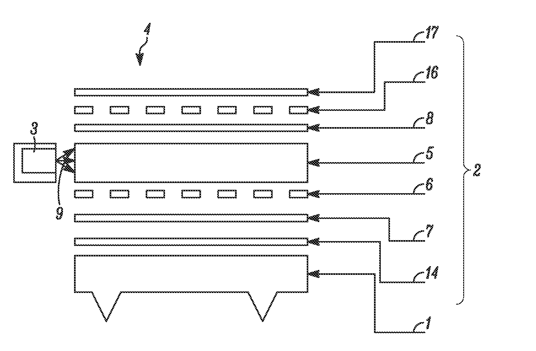
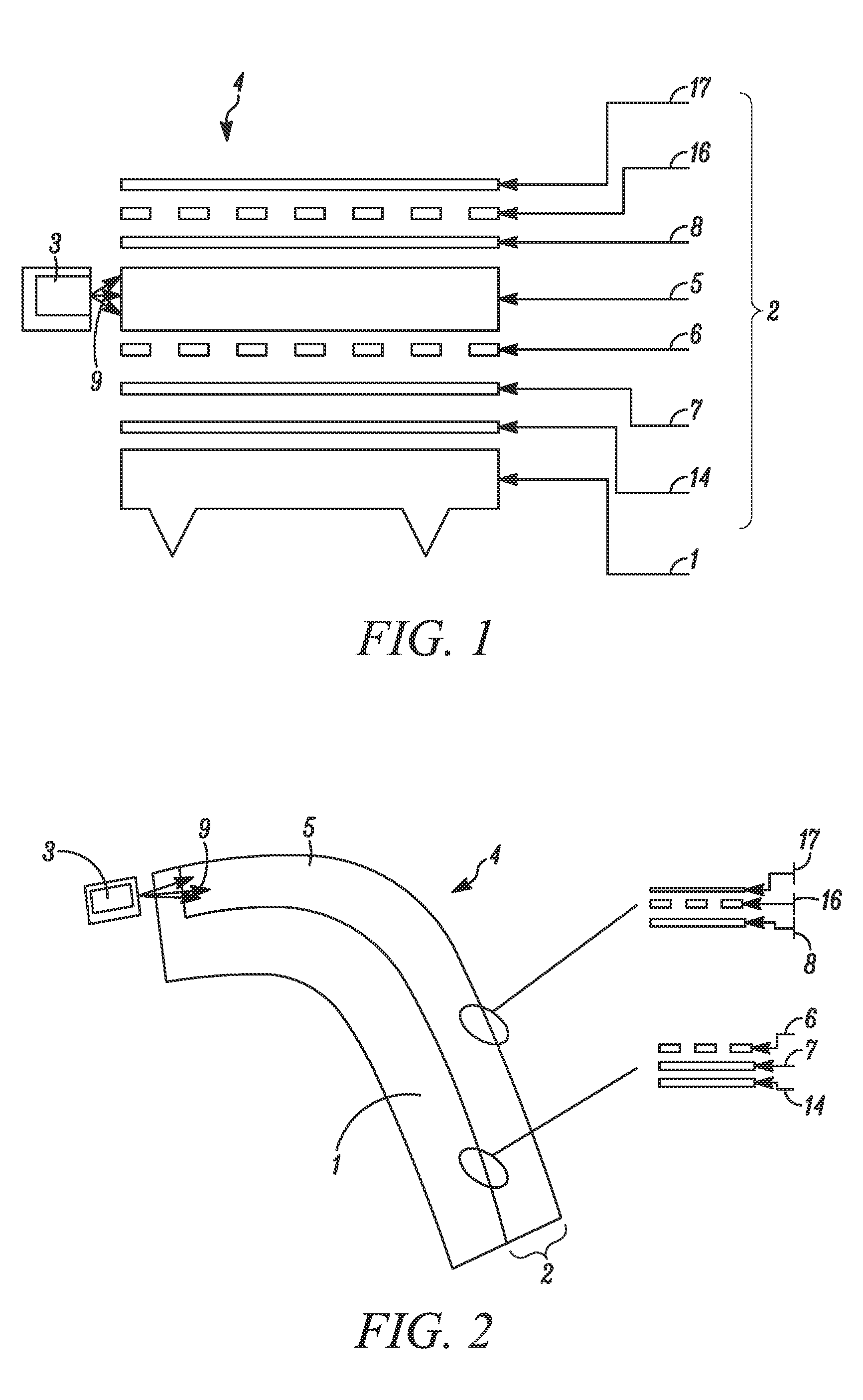
[0048]FIG. 2 shows a sectional view of an equipment part according to the present disclosure. The equipment part can include a transparent carrier 1 which may be made of polycarbonate, on which the composite film 2 can be disposed. The contour of the equipment part may be predefined by the carrier 1. The composite film 2 can have an overall thickness of 1.9 mm and may conform to the curves of the contour of the carrier 1. The light-conducting properties or the outcoupling behavior of the incoupled light rays 9 may not be impaired here. In the shown embodiment, the homogeneous outcoupling behavior may be additionally supported by a scatter layer 6, where the scatter layer 6 may have a surface structure that differs in various regions of the composite film. For example, the scatter layer 6 can have a considerably less pronounced surface structure in the curvature of the equipment part than in the planar regions.

[0049]Like the carrier 1, the light-conducting layer 5 of the composite fi...

second embodiment

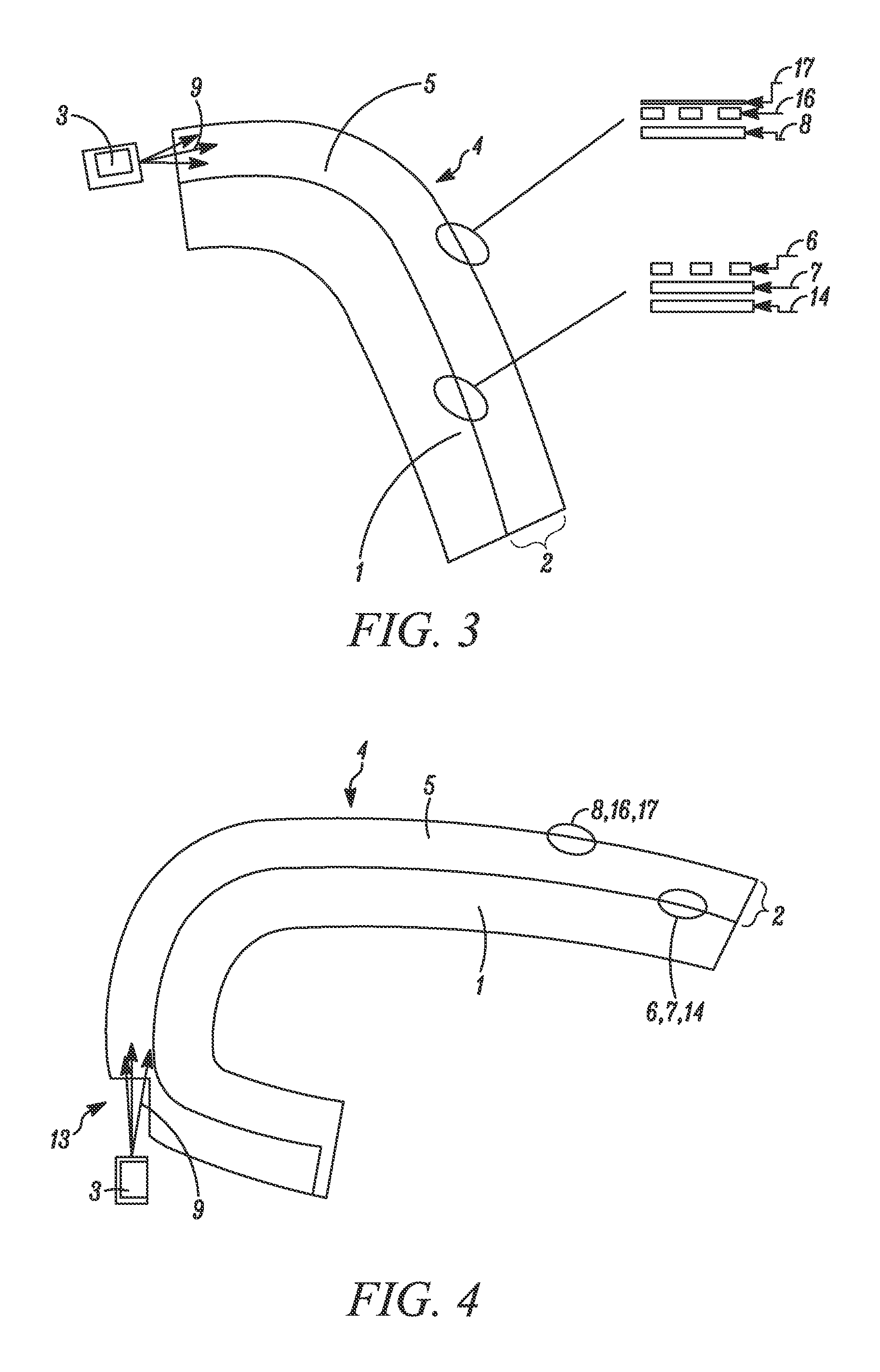
[0050]FIG. 3 shows a sectional view of the equipment part according to the present disclosure. The carrier 1 can be made of non-transparent polypropylene. In addition to polycarbonate and polypropylene, it is also possible to use other plastic materials, such as polyethylene, polymethyl methacrylate or acrylonitrile butadiene styrene, for example, for forming the carrier. In this embodiment, the light rays 9 of the light source 3 may be no longer able to penetrate the carrier 1, so the carrier 1 can be removed in an end-face region of the composite film 2 using a milling cutter. However, the material removal can also be carried out by way of drilling, cutting, or other comparable material-removing processes. The composite film 2 may comprise a white protective coating 14. Plastic material that has a sufficiently low melting temperature may be used, and the protective coating 14 may thereby be dispensed with. If the carrier 1 is additionally dyed in a white color or in another easily...

third embodiment

[0052]FIG. 4 shows an equipment part according to the present disclosure. The equipment part may have an edge folding, so that an undercut region can be created, which may not be visible to the observer of the equipment part. Such a design may be necessary, for example, if additional equipment parts directly adjoin the equipment part. It can therefore be avoided that potential gaps or even omissions between the equipment parts are visible. Moreover, such an edge folding may be provided for attaching the equipment part. An opening 13 can be introduced into the composite film 2, which may serve an incoupling point for the light source 3. For this purpose, the second paint layer 8, the imprint 16, and the protective layer 17 can be completely removed in the undercut region. Moreover, a step, which may form the opening 13, can be introduced into the light-conducting layer 5 with the aid of a milling process, for example. The light source 3 may moreover be provided directly in front of t...


PUM

PropertyMeasurementUnit
thicknessaaaaaaaaaa
thicknessaaaaaaaaaa
thicknessaaaaaaaaaa

Abstract

The present invention relates to an equipment part, in particular for a motor vehicle, comprising a carrier (1), a composite film (2), and a light source (3). The composite film (2) is disposed on the carrier (1) and forms the visible side (4) of the equipment part. The composite film (2) comprises a light-conducting layer (5), a scatter layer (6), and two paint layers (7, 8), so that light rays (9) generated by the light source (3) can be coupled into the composite film, and the visible side (4) of the equipment part is extensively illuminated with the aid of the composite film (2). The present invention further comprises a method for the production of such an equipment part.

Description

CROSS-REFERENCE TO RELATED APPLICATION[0001]This application is based upon and claims the benefit of prior German Application No. 10 2014 112 470.7, filed on Aug. 29, 2014, the entire contents of which are incorporated herein by reference.TECHNICAL FIELD[0002]The present disclosure relates to an equipment part that may comprise a carrier, a composite film, and a light source, wherein the composite film forms the visible side of the equipment part and can be illuminated by way of the light source. The present disclosure further relates to the production of such an equipment part.BACKGROUND OF THE DISCLOSURE[0003]In addition to functionality, in the present day and age, the outer and inner appearance of the motor vehicle plays an increasingly more important role. In addition to upscale decors, equipment parts are increasingly provided with light guides and light sources that illuminate the equipment part. Injection-molded planar light guides, for example, are frequently used on equipm...

Claims


Application Information

Patent Timeline
Patent Type & Authority Applications(United States)
IPC IPC(8): F21V8/00
CPCG02B6/005G02B6/0073G02B6/0065
Inventor WIMMER, MARKUSWINKLBAUER, MANFREDJUSTUS-BISCHLER, ELENALANG, JOSEFBAYERSDORFER, BERNHARDLURZ, JOSEF
Owner LISA DRAXLMAIER GMBH
Why Eureka
Try Eureka