Novel tensile special cable

A special cable and tensile technology, applied in the direction of insulated cables, cables, circuits, etc., can solve the problems of impact, poor impact resistance and compression performance, easy damage to the cable core, etc., so as to reduce the influence of self-weight and improve fire resistance. , to ensure the effect of power-on performance

Pending Publication Date: 2019-01-01
GUIZHOU XINSHUGUANG CABLE CO LTD
View PDF0 Cites 2 Cited by
  • Summary
  • Abstract
  • Description
  • Claims
  • Application Information

AI Technical Summary

Problems solved by technology

[0003] With the rapid development of society, cables, as an important product of electric energy transmission, have also obtained rapid and effective development. The fireproof cables in the prior art are mainly composed of outer sheath layers, metal conductors, fire-resistant layers and flame-retardant filling materials. Although The conduction function can be realized at a relatively certain temperature and degree of ignition, but the products produced by the current cable technology have poor stability in use, and the fire prevention effect is not obvious, and the impact resistance and compression resistance are very poor. It affects the applicability of the cable; moreover, most of the current cables are relatively simple in structure, and are prone to moisture, corrosion, impact, and pressure damage in some special occasions, and their service life is not long. Among them, most of the cable protection is composed of bimetallic steel strips or steel wires, usually one layer. When used in some environments, the protection of the cable core is not enough, especially when it is subjected to external impact pressure, it is easy to damage the cable. Core, affect the normal use of the cable
Moreover, the cost of erecting poles in some special occasions is relatively high, which requires a cable with better tensile resistance to reduce the cost of cable erection

Method used


Image

  • Novel tensile special cable

Examples


Embodiment Construction

[0026] The technical solutions in the embodiments of the present invention are clearly and completely described below in conjunction with the accompanying drawings. Apparently, the described embodiments are only a part of the embodiments of the present invention, not all of them.

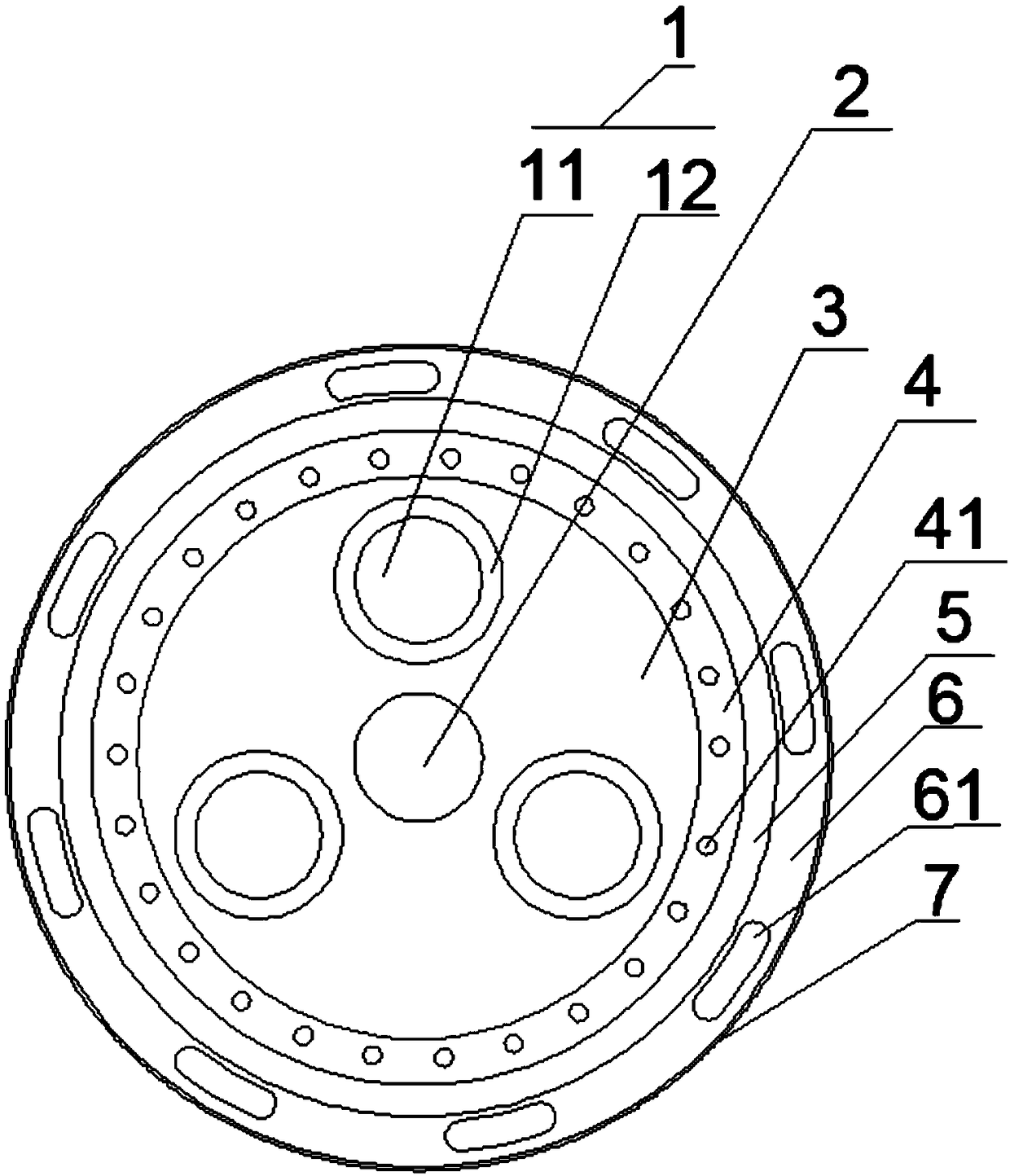
[0027] refer to figure 1 , a new type of tensile special cable, comprising at least one conductor unit 1, a tension cable 2 and a filling layer 3, the conductor unit 1 includes a cable core 11 and a phase-separated insulating layer 12, and the phase-separated insulating layer 12 is surrounded and arranged outside the cable core 11;

[0028] The tension cable 2 is located at the center of the cable, the filling layer 3 is arranged outside the tension cable 2, and the conductor unit 1 is distributed around the tension cable 2 in the filling layer 3, and the filling layer 3 is far away from the tension cable. One side of the cable 2 is provided with a fireproof isolation layer 4, and the side of the f...


PUM


Abstract

The invention discloses a novel tensile special cable, and the cable comprises at least one conductor unit, a tensile cable and a filling layer. The conductor unit comprises a cable core and a split-phase insulating isolation layer, wherein the split-phase insulating isolation layer is set around the cable core. The tensile cable is located at the center of the cable, and the filling layer is disposed outside the tensile cable. The conductor units are arranged around the tensile cable, and are distributed in the filling layer. One side, far from the tensile cable, of the filling layer is provided with a fireproof isolation layer, and one side, far from the tensile cable, of the fireproof isolation layer is provided with a reinforcing layer. One side, far from the fireproof isolation layer,of the reinforcing layer is provided with an impact-resistant layer, and one side, far from the reinforcing layer, of the impact-resistant layer is provided with an outer protection sheath. The reinforcing layer comprises a flame-retardant oxygen isolating layer and an armored layer wrapping the flame-retardant oxygen isolating layer in an annular manner.

Description

technical field [0001] The invention relates to the technical field of electric wires and cables, in particular to a novel tensile special cable. Background technique [0002] The full name of aramid fiber is "polyphenylene phthalamide", and it is Aramid fiber in English. It is a new type of high-tech synthetic fiber with excellent properties such as ultra-high strength, high modulus, high temperature resistance, acid and alkali resistance, and light weight. , its strength is 5 to 6 times that of steel wire, its modulus is 2 to 3 times that of steel wire or glass fiber, its toughness is 2 times that of steel wire, and its weight is only about 1 / 5 of that of steel wire. Decomposes, does not melt. It has good insulation and anti-aging performance, and has a long life cycle. The discovery of aramid fiber is considered to be a very important historical process in the material industry. [0003] With the rapid development of society, cables, as an important product of electric...

Claims


Application Information

Patent Timeline
Patent Type & Authority Applications(China)
IPC IPC(8): H01B7/18H01B7/02H01B7/24H01B7/295H01B7/282H01B3/47
CPCH01B3/47H01B7/0258H01B7/1895H01B7/24H01B7/2825H01B7/295Y02A30/14
Inventor 余宇潘刚
Owner GUIZHOU XINSHUGUANG CABLE CO LTD
Why Eureka
Try Eureka