Sensor and guide wire assembly

a technology of guide wires and sensors, applied in the direction of guide wires, sensors, medical science, etc., can solve the problems of difficult alignment and centrement of the jacket and the first and second coils with respect, low strength of joints, and relatively time-consuming procedures, and achieve reliable joints, large attachment area, and reliable attachment

Active Publication Date: 2018-04-24
ST JUDE MEDICAL COORDINATION CENT
View PDF14 Cites 3 Cited by
  • Summary
  • Abstract
  • Description
  • Claims
  • Application Information

AI Technical Summary

Benefits of technology

[0008]An object of the present invention is to remedy at least some of the problems encountered with a jacket according to the prior art. This object is accomplished by providing a jacket with at least one end portion having such mechanical properties that it can be crimped onto a core wire. By crimping an end portion of the jacket onto the core wire, a reliable attachment is achieved without the use of glue or solder. The outer diameter of the end portion after the crimping is preferably adapted to the inner diameter of a coil to be attached to the jacket. The coil can thereby be threaded onto the crimped end portion of the jacket, such that a large contact area between the coil and the jacket is provided. Preferably, the coil is then glued or soldered to the crimped end portion, and—as a result of the large attachment area—a very reliable joint has been accomplished.
[0009]A further advantage with the present jacket is that by adapting the outer diameter of the jacket after crimping to the inner diameter of a coil, the coil and the jacket are self-centred with respect to each other, something which both facilitates the manufacturing procedure and provides a sensor and guide wire assembly without any radially protruding step portions, which otherwise could arise from a mismatch between the jacket and an adjoining coil. To achieve a smooth outer surface of the sensor and guide wire assembly, the outer diameter of the middle portion of the jacket, which is not crimped, should be adapted to the outer diameters of the coils. After crimping of an end portion of a jacket, the surface of the jacket has thereby been provided with a circumferential edge, which provides a natural stop against which a coil can come to rest after having been threaded onto a crimped portion. Such a stop will further facilitate the manufacturing of a sensor and guide wire assembly.

Problems solved by technology

A small contact area implies that the corresponding attachment area for a glue (or solder) provided between the jacket and the coil also is small, which consequently results in a joint whose strength is far from the maximum possible strength.
Another problem is that it can be difficult to align and centre the jacket and the first and second coils with respect to each other, such that a smooth transition is provided between the end of a jacket and the opposing end of a coil.
It has further now been realized that a manufacturing step that involves the manual gluing of a jacket to a portion of a core wire is a relatively time consuming procedure; and the strength of the resulting joints will vary over time and will also differ from one operator to another.
Similar disadvantages would also appear for a corresponding soldering procedure.

Method used


Image

  • Sensor and guide wire assembly
  • Sensor and guide wire assembly
  • Sensor and guide wire assembly

Examples


Embodiment Construction

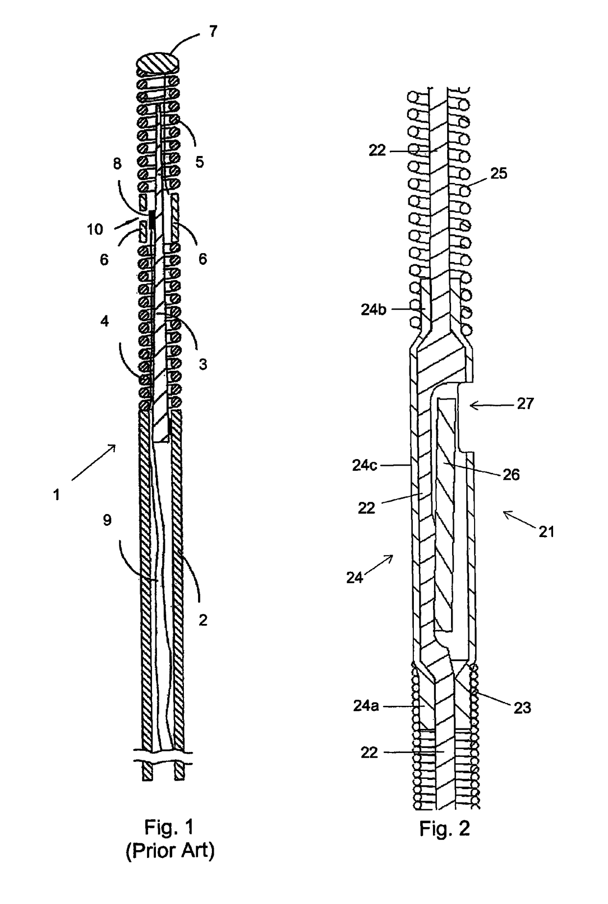
[0015]For better understanding of the context in which the present invention is going to be used, a sensor and guide wire assembly 1 of a conventional design is illustrated in FIG. 1. The sensor guide 1 comprises a hollow tube 2, a core wire 3, a first coil 4, a second coil 5, a jacket or sleeve 6, a dome-shaped tip 7, a sensor element or chip 8, and one or several electrical leads 9. The proximal end of the first coil 4 is attached to the distal end of the hollow tube 2, while the distal end of the first coil 4 is attached to the proximal end of the jacket 6. The proximal end of the second coil 5 is connected to the distal end of the jacket 6, and the dome-shaped tip 7 is attached to the distal end of the second coil 5. The core wire 3 is at least partly disposed inside the hollow tube 2 such that the distal portion of the core wire 3 extends out of the hollow tube 2 and into the second coil 5. The sensor element 8 is mounted on the core wire 3 at the position of the jacket 6, and ...


PUM


Abstract

The invention relates to a sensor and guide wire assembly (21) for intravascular measurements of physiological variables in a living body, comprising a core wire (22), a first coil (23), a jacket (24), and a second coil (25). The jacket (24) comprises a first end portion (24a), which is crimped onto the core wire (22) and over which a portion of the first coil (23) is threaded, and a second end portion (24b), which is crimped onto the core wire (22) and over which a portion of the second coil (25) is threaded.

Description

FIELD OF THE INVENTION[0001]The present invention relates generally to sensor and guide wire assemblies, in which a sensor element is mounted at the distal end of a guide wire for intravascular measurements of physiological variables in a living body, and particularly to the mounting arrangement of the sensor element, and more particularly to a jacket in which the sensor element is arranged.BACKGROUND OF THE INVENTION[0002]Sensor and guide wire assemblies in which a sensor is mounted at the distal end of a guide wire are known. In U.S. Pat. Re. 35,648, which is assigned to the present assignee, an example of such a sensor and guide wire assembly is disclosed, where a sensor guide comprises a sensor element, an electronic unit, a signal transmitting cable connecting the sensor element to the electronic unit, a flexible tube having the cable and the sensor element disposed therein, a solid metal wire, and a coil attached to the distal end of the solid wire. The sensor element comprise...

Claims


Application Information

Patent Timeline
Patent Type & Authority Patents(United States)
IPC IPC(8): A61B5/0215A61B5/00A61M25/09A61M25/00A61M25/01
CPCA61B5/0215A61B5/6851A61M25/09A61M2025/09175A61M2025/0002A61M2025/09083
Inventor SMITH, LEIFHAMMARSTROM, OLAEGNELOV, PERANG.KERFELDT, DAN
Owner ST JUDE MEDICAL COORDINATION CENT
Why Eureka
Try Eureka