Clutch exhaust assembly and method

Active Publication Date: 2008-09-18
GM GLOBAL TECH OPERATIONS LLC
View PDF5 Cites 4 Cited by
  • Summary
  • Abstract
  • Description
  • Claims
  • Application Information

AI Technical Summary

Benefits of technology

[0008]In another aspect of the invention, a method is provided for reducing clutch wear in a rotatable clutch assembly having a clutch-apply cavity and balance cavity, the method including configuring the balance cavity with an exhaust channel for exhausting fluid from the balance cavity and providing the exhaust channel with a control radius determined by the innermost radius of rotating fluid in the balance cavity with respect to the centerline of rotation of the assembly, the control radius being suitable for exhausting any excess of centrifugal balance force over centrifugal apply force.

Problems solved by technology

However, when the clutch reaches a relatively high rotational speed, the centrifugal force imparted by the rotation of the clutch housing may induce a substantial pressure head or centrifugal apply force within the clutch-apply cavity.
If the centrifugal apply force exceeds the return spring force provided by the biasing spring, inadvertent or premature application of the clutch may result.

Method used


Image

  • Clutch exhaust assembly and method
  • Clutch exhaust assembly and method
  • Clutch exhaust assembly and method

Examples


Embodiment Construction

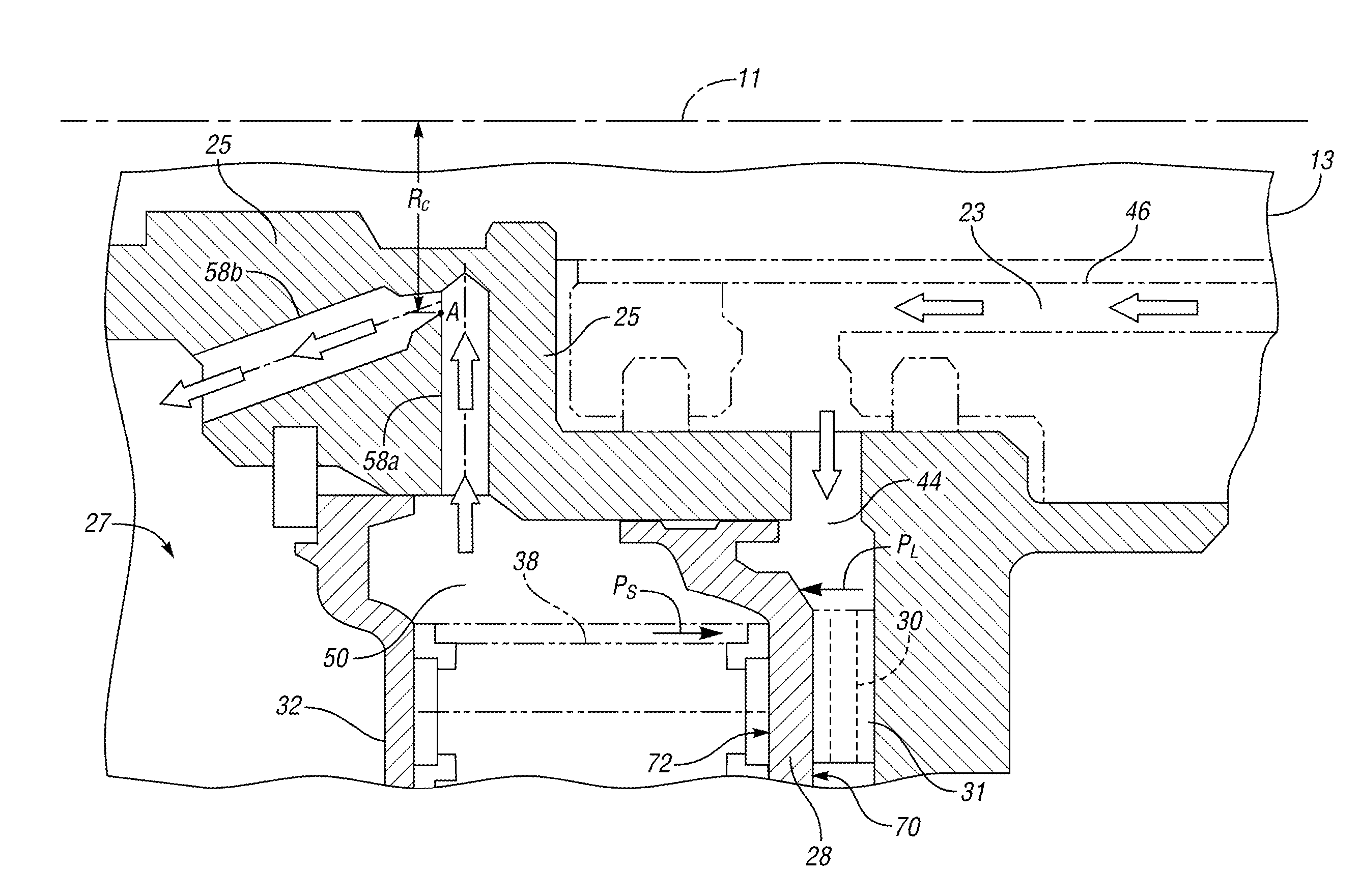
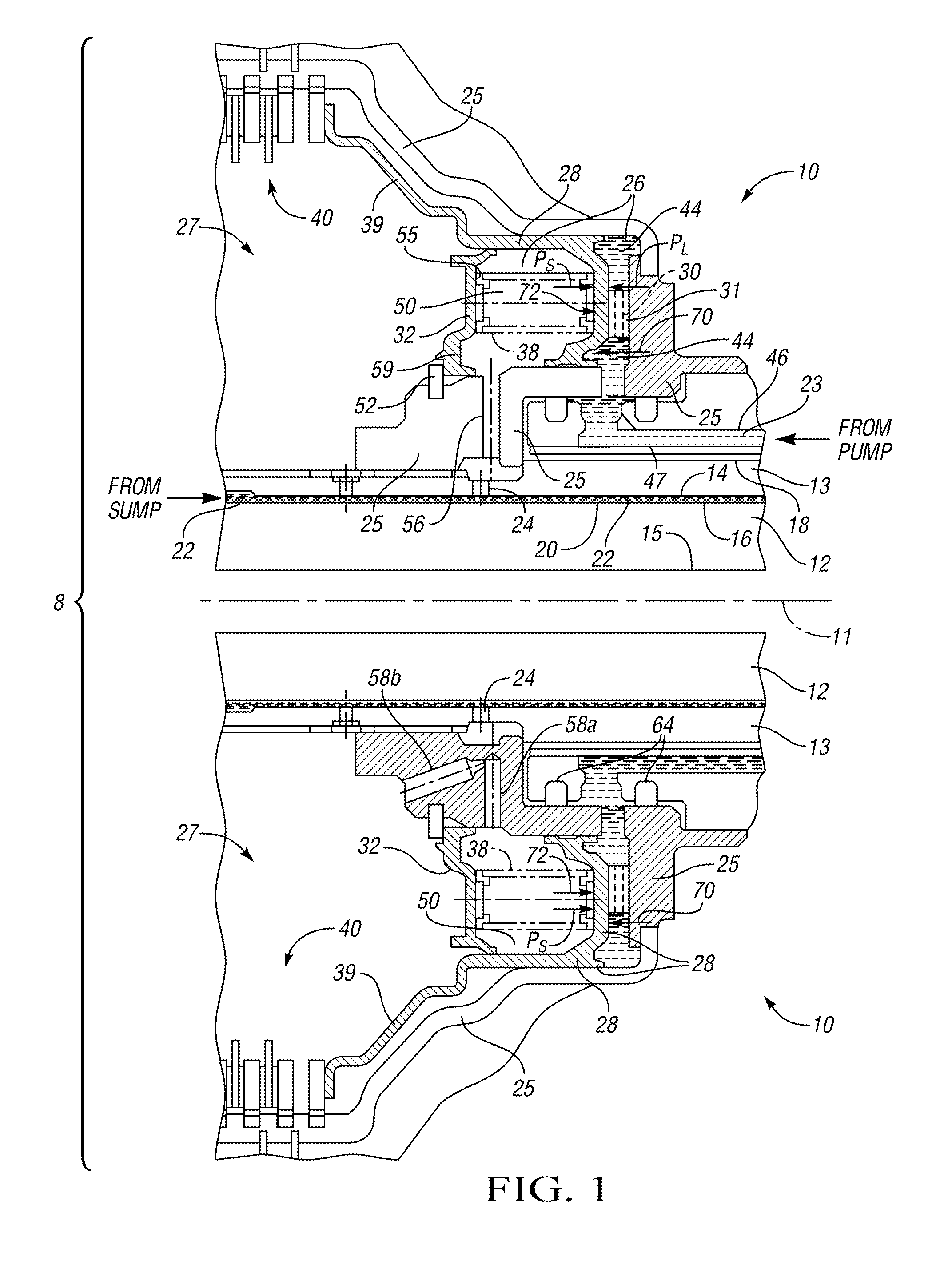
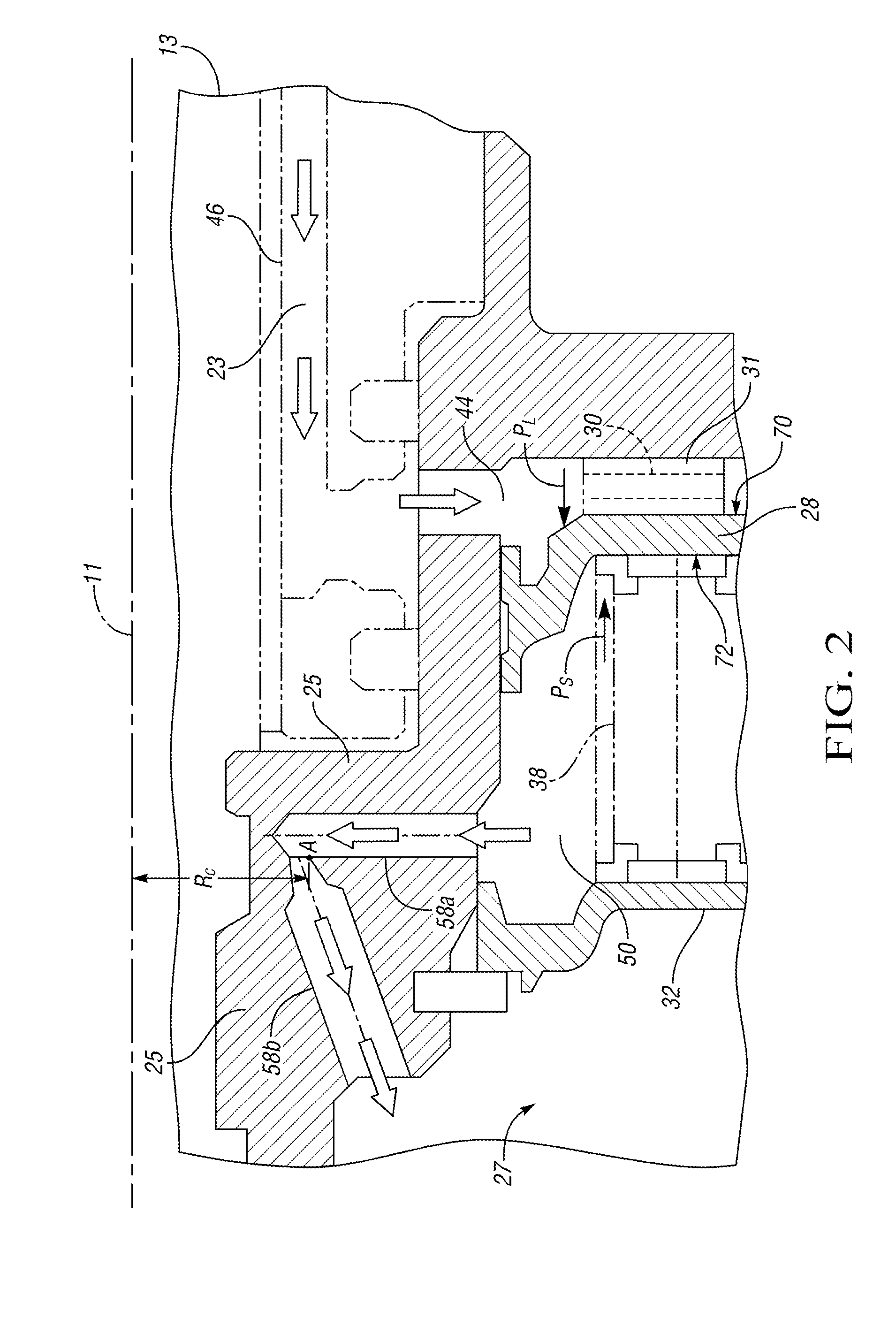
[0012]Referring to the drawings wherein like reference numbers correspond to like or similar components throughout the several figures, there is shown in FIG. 1 a cross-sectional view of a transmission 8 having a rotatable clutch assembly 10 mounted with respect to a pair of rotatable components such as co-axial inner and outer shafts 12, 13, respectively, which are rotatable around or with respect to a centerline 11. Centerline 11 divides FIG. 1 into upper and lower halves showing staggered cross-sectional views taken along different planes to more clearly depict the internal detail of clutch assembly 10. Rotatable shafts 12, 13 have respective internal diameters or surfaces 15, 14, and respective outer diameters or surfaces 16, 18, with a cylindrical channel or volume 20 defined between shaft surfaces 14, 16. Volume 20 is in fluid communication with a non-pressurized source of fluid 22, such as a transmission reservoir or sump (not shown). The fluid 22, such as transmission fluid,...


PUM


Abstract

An assembly and method is provided for reducing clutch wear due to centrifugal apply pressure within a clutch-apply cavity. The assembly comprises a rotatable clutch housing, a clutch-apply piston disposed within a clutch-apply cavity, and a balance piston. The balance and apply pistons define a balance cavity including a liquid fill channel and a dedicated air exhaust channel having a control radius configured to at least partially offset or compensate for the centrifugal apply force generated within the clutch-apply cavity when the clutch assembly rotates. The method includes configuring the balance cavity with an exhaust channel for exhausting fluid, and providing the exhaust channel with a control radius determined by the innermost radius of rotating fluid within the balance cavity as measured with respect to the centerline of rotation of the clutch assembly, the control radius being suitable for exhausting any excess of centrifugal balance force over centrifugal apply force.

Description

TECHNICAL FIELD[0001]The present invention relates to an improved rotatable clutch assembly having at least one dedicated balance cavity exhaust port configured to optimize clutch performance during rapid acceleration and periods of high clutch rotational speed.BACKGROUND OF THE INVENTION[0002]In a vehicle having an automatic transmission, a clutch assembly engages or couples a rotating shaft such as an engine crankshaft with a stationary shaft such as a driveshaft in order to transmit power from the engine to the drive wheels. Likewise, the clutch assembly disengages the respective shafts to interrupt the power transfer and permit smooth shifting between, for example, the various gears of a planetary gear set. Hydraulic clutch assemblies or hydraulic clutches in particular are hydraulically-actuated torque-transmitting devices typically having a series of friction elements arranged in a clutch pack within a clutch housing. The clutch pack is actuated by a clutch-apply piston dispos...

Claims


Application Information

Patent Timeline
IPC IPC(8): F16D25/12
CPCF16D25/123F16D25/0638
Inventor RASZKOWSKI, JAMES A.FOSTER, MICHAEL D.BECKNER, KEVIN C.
Owner GM GLOBAL TECH OPERATIONS LLC
Why Eureka
Try Eureka