Article conveying device

a conveying device and conveying technology, applied in mechanical conveyors, packaging, liquid handling, etc., can solve the problems of breaking the gripper, and unable to process plastic bottles in the filling device, etc., and achieve the effect of not increasing the size of equipmen

Active Publication Date: 2008-09-18
SHIBUYA IND CO LTD +1
View PDF7 Cites 15 Cited by
  • Summary
  • Abstract
  • Description
  • Claims
  • Application Information

AI Technical Summary

Benefits of technology

[0011]In view of the above problems, the present invention provides an article conveying device in which even if one rota

Problems solved by technology

First, in the case of Patent Document 2, when rotation of the star-shaped conveying wheel 7 is continued in the state in which the molding device abnormally stops and the star-shaped conveying wheel 6 stops, there arises the fear that the plastic bottle gripped by the gripper of the star-shaped conveying wheel 6 and the gripper of the star-shaped conveying wheel 7 interfere with each other in the above described delivery position of the plastic bottles, and the gripper is broken.
Therefore, when the molding device abnormally stops, the

Method used


Image

  • Article conveying device
  • Article conveying device
  • Article conveying device

Examples


second embodiment

[0124]Next, a second embodiment according to the present invention will be described by using FIG. 9. The members common to those in the above described first embodiment will be described by adding 100 to each of the reference numerals used in the first embodiment.

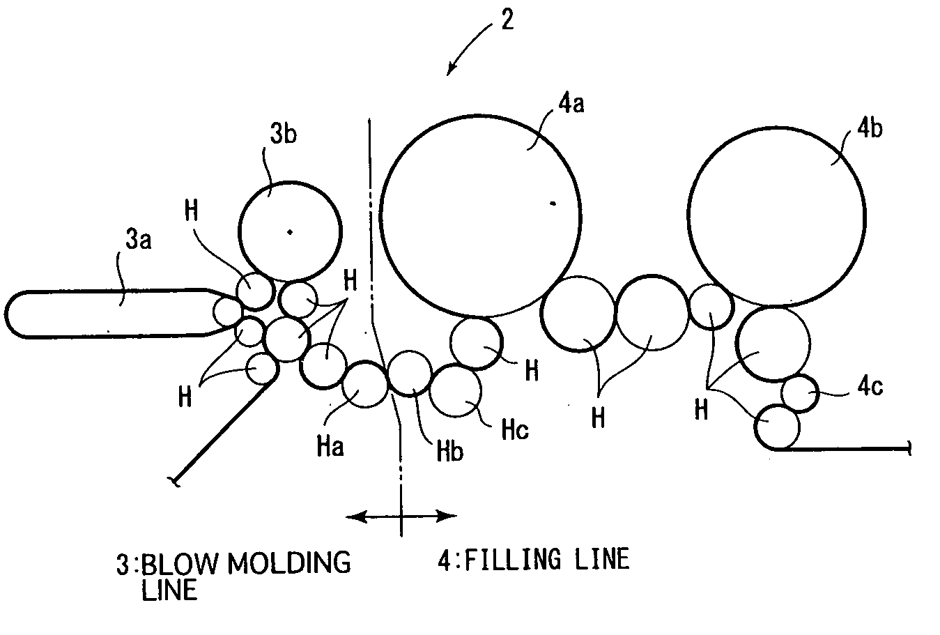
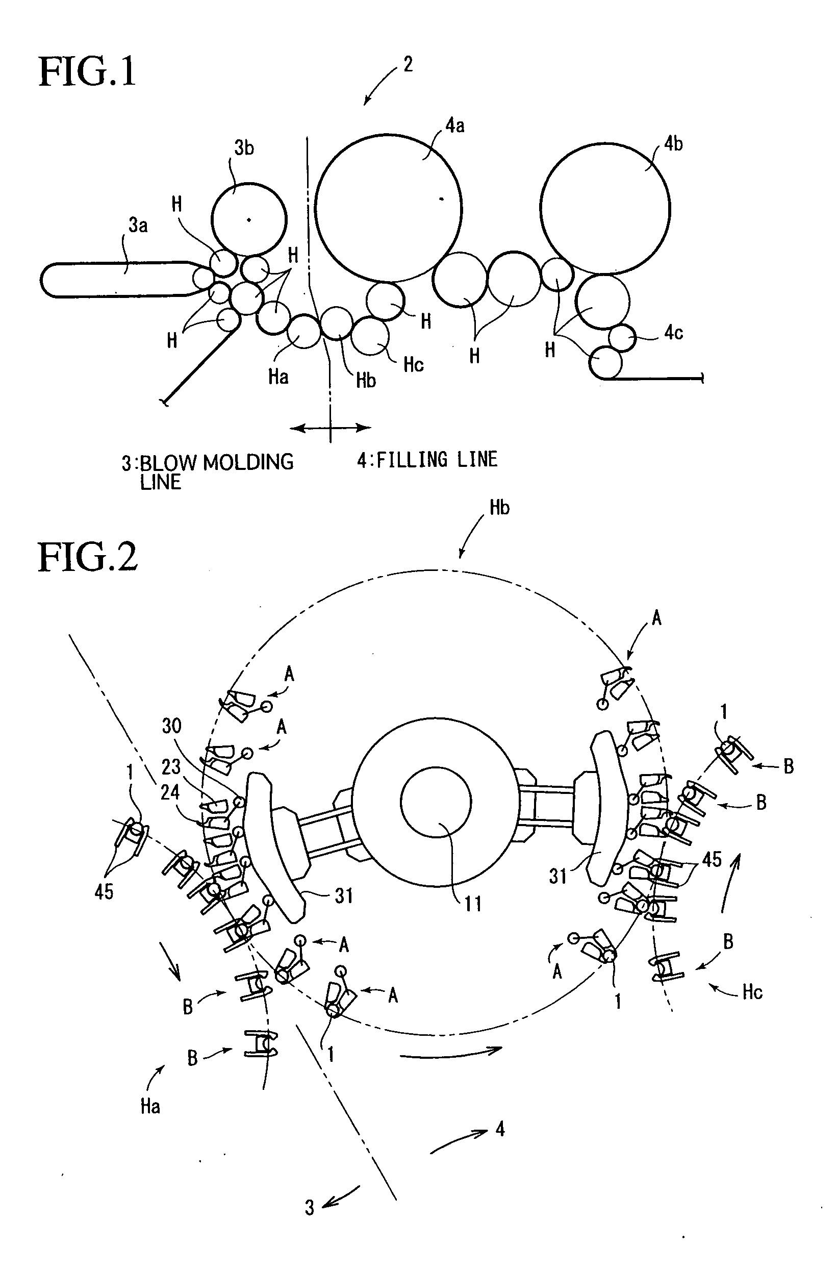
[0125]In the above described first embodiment, the grippers A each having the opening and closing mechanism are provided at the downstream side wheel Hb, but a beverage manufacturing line 2 of the second embodiment adopts a constitution in which the grippers A each having the opening and closing mechanism are provided at the upstream side wheel Ha and the grippers B which do not perform opening and closing operations for themselves are provided at the downstream side wheel Hb.

[0126]The upstream side wheel Ha in this embodiment includes the grippers A and the retreating means C having the same constitutions as those of the grippers A and the retreating means C in the above described first embodiment, and the downstream side...

third embodiment

[0136]Next, a third embodiment according to the present invention will be described by using FIGS. 10 and 11.

[0137]In this third embodiment, the constitutions of the gripper A and the retreating means C differ from those of the above described first embodiment. The difference will be described hereinafter, and the members corresponding to respective members of the above described first embodiment will be described by adding 200 to each of the reference numerals used in the first embodiment.

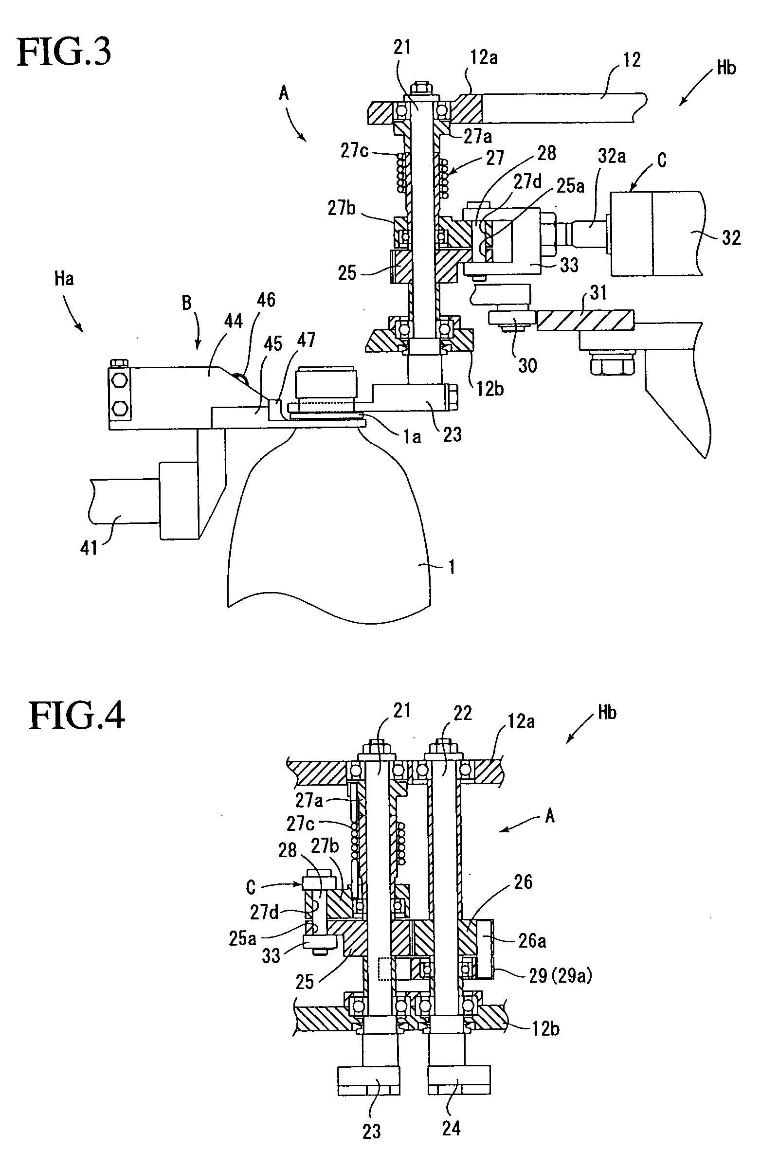
[0138]The gripper A has an opening and closing mechanism, and includes a first grip member 223 fixed to a first rotary shaft 221, a second grip member 224 fixed to a second rotary shaft 222, a first gear member 225 fixed to the first rotary shaft 221, a second gear member 226 fixed to the second rotary shaft 222, and biasing means not illustrated which is provided at the above described first rotary shaft 221 to bias the first and second grip members 223 and 224 in a closing direction.

[0139]The se...

fourth embodiment

[0150]Next, by using FIG. 12, a fourth embodiment according to the present invention will be described. In the following description, the members corresponding to the respective members of the above described first embodiment will be described by adding 300 to each of the reference numerals used in the first embodiment.

[0151]The upstream side wheel Ha of this embodiment is provided with the grippers A each having an opening and closing mechanism, and the downstream side wheel Hb is provided with the grippers B which have the same constitutions as the grippers B in the above described first embodiment and do not perform opening and closing operations for themselves.

[0152]In this embodiment, the retreating means C is provided at the gripper B which does not perform an opening and closing operation for itself.

[0153]The retreating means C includes an air cylinder 351 provided at a rotary table 312, a cylindrical bearing member 353 fixed to the rotary table 312 via a stay 352, and a movi...


PUM


Abstract

An upstream side wheel Ha including grippers B which do not perform opening and closing operations for themselves, and a downstream side wheel Hb including grippers A each having an opening and closing mechanism are included, and in a delivery position in which both the wheels are adjacent to each other, a plastic bottle 1 is delivered from the gripper B to the gripper A. Here, if the upstream side wheel or the downstream side wheel abnormally stops, control means controls retreating means C provided at the downstream side wheel to switch the grippers A to a retreat state from a use state to make an opening degree of a first and second grip members 23 and 24 of each of the grippers A larger than an opening degree of both the grip members in the use state. Thereby, interference of the plastic bottles gripped by the upstream side grippers and the first and second grip members can be prevented. Even if one of the wheels abnormally stops, the other wheel can be continuously operated without increasing the equipment in size.

Description

FIELD OF THE INVENTION [0001]The present invention relates to an article conveying device, and particularly relates to an article conveying device which delivers articles to grippers of a rotary wheel at a downstream side from grippers of a rotary wheel at an upstream side in a delivery position in which the rotary wheels are adjacent to each other.DESCRIPTION OF THE PRIOR ART [0002]Conventionally, in a beverage manufacturing line which carries out molding of, for example, plastic bottles as articles to filling of beverage, a molding device for molding the plastic bottles and a filling device for filling beverage or the like into the plastic bottles are included, and the molding device and filling device are provided-with an article conveying device for conveying the plastic bottles (Patent Documents 1 and 2).[0003]Of them, as the article conveying device of Patent Document 1, a conveying device 3 for conveying plastic bottles is provided between the molding device and the filling d...

Claims


Application Information

Patent Timeline
IPC IPC(8): B65G47/86
CPCB65G29/00B65G2201/0247B65G47/847B67C3/242B67C7/0053
Inventor NISHI, TOKUOKAYA, KOJINAKADA, TATSUHIRONISHIKAWA, HIDEKISHIMOMURA, TAKASHI
Owner SHIBUYA IND CO LTD
Why Eureka
Try Eureka