Method of and Software for Calculating a Scatter Estimate for Tomographic Scanning and System for Tomographic Scanning

a technology of tomographic scanning and scatter estimation, applied in the field of software for calculating the scatter estimate for tomographic scanning and the system for tomographic scanning, can solve the problem of inaccuracy of the estimate of the higher-order scatter, and achieve the effect of reducing the computation time of the scatter simulation, reducing the time, and less spatial structur

Inactive Publication Date: 2008-09-18
HAMMERSMITH IMANET
View PDF5 Cites 21 Cited by
  • Summary
  • Abstract
  • Description
  • Claims
  • Application Information

AI Technical Summary

Benefits of technology

[0020]In a special embodiment of the method elements of the calculation are cached prior to calculation of the scatter estimate. The prior calculation and storage of the elements reduces the computation time of the scatter simulation, thereby reducing the time between the data acquisition and the availability of the reconstructed image of the subject. The elements are preferably attenuation coefficients and / or detection probabilities. The latter includes two terms; one angle dependent and one angle independent term of the detection probabilities. Elements such as the detection probability and the scatter probability may be cached as a function of photon energy. When the grid of points used in the simulation is known, not only the scatter probabilities but also the scatter angles may be cached before the simulation.
[0021]In an advantageous embodiment of a method for calculating a first estimate for nth order scatter and a second estimate for (n+1)th order scatter, where n is an integer equal to or larger than one, the calculation of the first estimate uses more detectors and / or scatter points than the calculation of the second estimate. Since higher order scatter shows less spatial structure than lower order scatter, the calculations for the higher order scatter estimate can be carried out using a reduced number of scatter points and / or detectors. The detectors and scatter points used for the second estimate are preferably a subset of the detectors and scatter points used for the first estimate, thereby allowing the reuse of elements in the calculation based on these detectors and scatter points.

Problems solved by technology

In most detector configurations there will be directions in which coincidences are not detectable due to the geometry of the detector array, since the scanner has a finite field of view and there may be blind spots due to gaps between the detectors.
A disadvantage of the known method for scatter correction is the inaccuracy of the estimate for the higher-order scatter.

Method used


Image

  • Method of and Software for Calculating a Scatter Estimate for Tomographic Scanning and System for Tomographic Scanning
  • Method of and Software for Calculating a Scatter Estimate for Tomographic Scanning and System for Tomographic Scanning
  • Method of and Software for Calculating a Scatter Estimate for Tomographic Scanning and System for Tomographic Scanning

Examples


Embodiment Construction

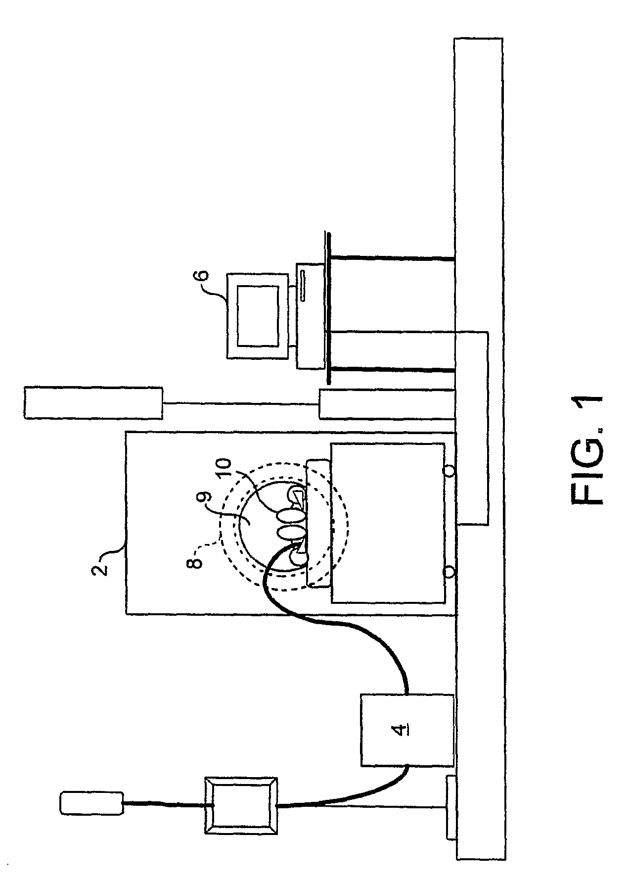
[0038]FIG. 1 shows a tomographic scanner system, arranged in accordance with an embodiment of the invention, which includes a PET scanner 2, a tracer generator module 4 and an operator computer terminal 6. The scanner 2 includes a detector array 8 arranged about a scanning area 9, in which a subject 10 is located during a transmission scan and during an emission scan.

[0039]One embodiment of the invention relates to a non-rotating PET scanner, for example, a PET scanner of the ECAT EXACT3D™ type. In this embodiment, the detectors in the detector array 8 are arranged in square detector blocks, each containing multiple detector elements. The detectors blocks are arranged in multiple rings, the rings being arranged adjacent one another along a scanner axis.

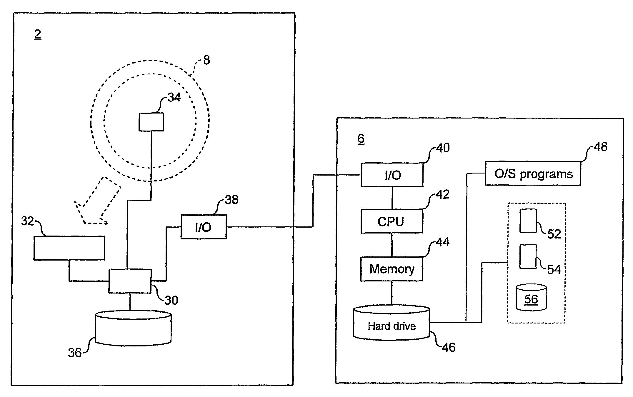
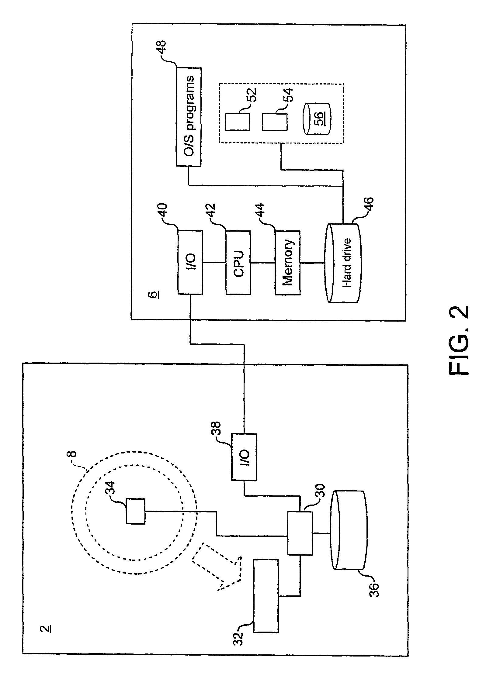
[0040]As shown in FIG. 2, the PET scanner 2 includes a control unit 30, processing circuitry 32 for detection data received from the detector array, a motion detector 34, a memory 36 for storing the detection data and movement data, a...


PUM


Abstract

The method calculates a scatter estimate for annihilation photons in a subject having a distribution of attenuation. The method can be used for scatter correction of detection data from a positron emission tomographic scanner. The method uses the following steps: —select a first scatter point S1 and a second scatter point S2, —determine a first scatter probability for scattering of a photon at scatter point S1 and a second scatter probability for scattering of a photon at scatter point S2, —determine an integral of the attenuation over a line connecting S1 and S2, —multiply the integral and the scatter probabilities and use the product in the calculation of the scatter estimate.

Description

FIELD OF THE INVENTION[0001]The invention relates to a method for calculating a scatter estimate for annihilation photons in a subject having a distribution of emission and attenuation for scatter correction of detection data from a positron emission tomographic scanner. The invention also relates to software carrying out the method, a data carrier comprising the computer software and a tomographic scanning system adapted for carrying out the method.BACKGROUND OF THE INVENTION[0002]A typical emission scan using a positron emission tomography (PET) scanner starts with the injection of a solution including a tracer into the subject to be scanned. The subject may be human or animal. The tracer is a pharmaceutical compound including a radioisotope with a relatively short half-life. The tracer has been adapted such that it is attracted to sites within the subject where specific biological or biochemical processes occur. The tracer moves to and is typically taken up in one or more organs ...

Claims


Application Information

Patent Timeline
Patent Type & Authority Applications(United States)
IPC IPC(8): G01T1/29G01T1/00G01T1/164
CPCG01T1/1647A61B6/037G01T1/2985
Inventor THIELEMANS, KRIS FILIP JOHAN JULESTSOUMPAS, CHARALAMPUS
Owner HAMMERSMITH IMANET
Why Eureka
Try Eureka