Crash box and bumper for a motor vehicle

a technology for motor vehicles and bumpers, applied in bumpers, vehicle safety arrangments, transportation and packaging, etc., can solve the problems of ineffective utilization of available space for energy absorption, deformation path, and low lateral stiffness of slide-in tubes of this type, so as to improve side stiffness, improve deformation and folding process, and adjust the stiffness of the collar

Inactive Publication Date: 2008-09-18
BENTELER AUTOMOBILTECHNIK GMBH
View PDF45 Cites 34 Cited by
  • Summary
  • Abstract
  • Description
  • Claims
  • Application Information

AI Technical Summary

Benefits of technology

[0013]The longitudinal profile rests with the collar upon the side-rail-distal side of the flange plate, i.e. on the flange plate side which is adjacent to the side rail, and is welded to the flange plate in this area. This may be realized by a continuous, circumferential welding seam, or intermittent welding seam, or spot welding seam. The stiffness of the collar may be adjusted by varying the geometric configuration of the collar, such as length of its marginal legs, radius of deformation and angle of the margin legs of the collar in relation to the body of the longitudinal profile. In this way, the functionally desired folding operation and its initialization can be controlled and triggered in the event of impact.
[0014]According to another feature of the present invention, the longitudinal profile may have rounded corners. The longitudinal profile is thus substantially rectangular with rounded length edges, as viewed in vertical cross section. As a result, side stiffness is further improved and positively affects the deformation and folding

Problems solved by technology

Slide-in tubes of this type afford only little lateral stiffness.
A problem common to conventional bumpers is the fact that the available space for energy

Method used


Image

  • Crash box and bumper for a motor vehicle
  • Crash box and bumper for a motor vehicle
  • Crash box and bumper for a motor vehicle

Examples


Embodiment Construction

[0033]Throughout all the figures, same or corresponding elements may generally be indicated by same reference numerals. These depicted embodiments are to be understood as illustrative of the invention and not as limiting in any way. It should also be understood that the figures are not necessarily to scale and that the embodiments are sometimes illustrated by graphic symbols, phantom lines, diagrammatic representations and fragmentary views. In certain instances, details which are not necessary for an understanding of the present invention or which render other details difficult to perceive may have been omitted.

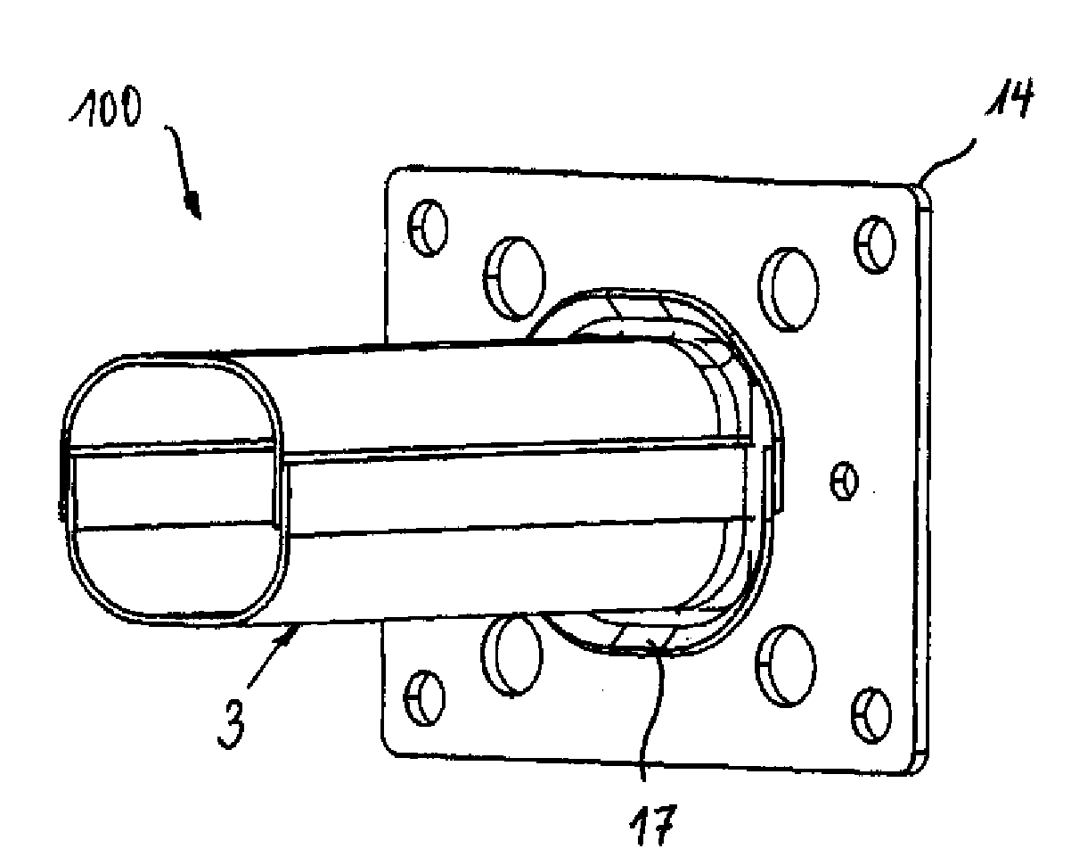
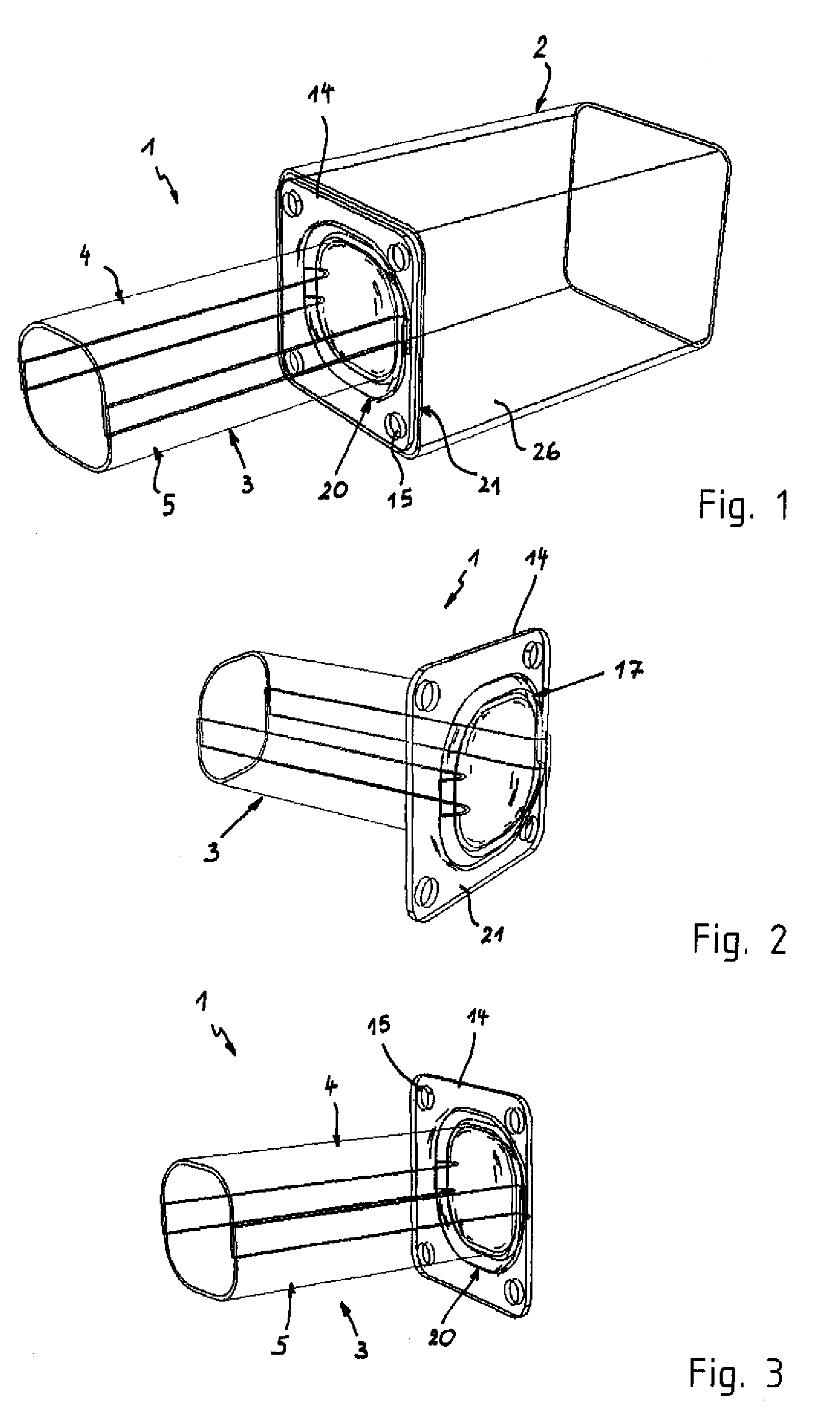
[0034]Turning now to the drawing, and in particular to FIG. 1, there is shown a fragmentary perspective view of a bumper structure having incorporated a crash box according to the present invention, generally designated by reference numeral 1, for attachment to a side rail 2 of a motor vehicle. The crash box 1 is arranged between an unillustrated bumper beam and the side rai...


PUM


Abstract

A crash box for placement between a bumper beam and a side rail of a motor vehicle includes a longitudinal profile made of two U-shaped shells having overlapping ends sized to realize a material doubling for increasing side stiffness and to suit the side stiffness to a load level. A flange plate is provided on a side-rail-proximal end of the longitudinal profile and has an opening for passage of the longitudinal profile. The side-rail-proximal end of the longitudinal profile is configured with a collar which is turned outwards. The collar rests against the flange plate and is joined with the flange plate. In the event of a collision, the longitudinal profile of the crash box is moved into the side rail as the longitudinal profile folds into the side rail starting from the flange plate, while the side-rail-proximal end of the longitudinal profile remains secured to the flange plate.

Description

CROSS-REFERENCES TO RELATED APPLICATIONS[0001]This application claims the priority of German Patent Application, Serial No. 10 2007 012 137.9, filed Mar. 12, 2007, pursuant to 35 U.S.C. 119(a)-(d), the content of which is incorporated herein by reference in its entirety as if fully set forth herein.BACKGROUND OF THE INVENTION[0002]The present invention relates to a crash box for placement between a bumper beam and a side rail of a motor vehicle, and to a bumper provided with such a crash box.[0003]Nothing in the following discussion of the state of the art is to be construed as an admission of prior art.[0004]A standard bumper is typically mounted on the front or rear of a motor vehicle to absorb impact energy and thereby prevent damage to the vehicle structure in the event of a frontal or rear impact. The bumper typically includes a bumper beam which is mounted to the side rails of the vehicle frame through intervention of crash boxes. The bumper beam is provided to introduce energ...

Claims


Application Information

Patent Timeline
IPC IPC(8): B60R19/26
CPCB60R19/34
Inventor WANG, HUIPAARE, MIRKOHANDING, CHRISTIAN
Owner BENTELER AUTOMOBILTECHNIK GMBH
Why Eureka
Try Eureka