Light outcoupling structure for a lighting device

Active Publication Date: 2008-09-18
MODILIS HLDG LLC
View PDF18 Cites 47 Cited by
  • Summary
  • Abstract
  • Description
  • Claims
  • Application Information

AI Technical Summary

Benefits of technology

[0021]An embodiment of the present invention incorporates interaction between consecutive diffractive surface relief forms of the outcoupling unit so that the overall coupling efficiency in the predetermined direction, i.e. light directivity, can be increased concerning the outcoupling system including a plurality of outcoupling units, not just a single outcoupling unit and its directivity. Each optical design may generally include a plurality of similar or different outcoupling units.
[0022]Typically, the desired outcoupling angle is, depending on the embodiment, narrow

Problems solved by technology

Power consumption and light pollution are both actual issues in all optical applications.
However, merely using the diffractive grating grooves doesn't automatically guarantee tolerable performance by any standard as to be reviewed hereinafter.
Major part of this light finally leaks out from the lightguide or is outcoupled at a non-preferred angle resulting non-directive output light and thus in many applications inferior lighting effect and low light coupling efficiency.
Notwithstanding the various prio

Method used


Image

  • Light outcoupling structure for a lighting device
  • Light outcoupling structure for a lighting device
  • Light outcoupling structure for a lighting device

Examples


Example

[0073]FIG. 4a illustrates, by way of example only, one embodiment of a lightguide arrangement wherein a plurality of different outcoupling units 404 are structured on the transparent lightguide surface area 401 and one or more light sources such as fluorescence lamps or LEDs, 402 are located adjacent to one end of the guide. The lines within the units 404 in this particular embodiment represent diffractive surface relief forms, such as grating grooves (or their “peaks”). The outcoupling units 402 may differ in size, shape, alignment, internal structures, materials, etc. Also, aggregate units including different kinds of sub-structures, such as linear, curved or wavy forms, can be utilized to efficiently direct light incident thereon. The distance between the adjacent outcoupling units may be varied based on a predetermined schema. For instance, as the intensity of light tends to drop when moving farther away from the light sources 402, the density of outcoupling units can be respect...


PUM


Abstract

A diffractive light outcoupling unit for forming a part of a directive light outcoupling system of a lighting device including a plurality of diffractive outcoupling units. The diffractive light outcoupling units each include a carrier element for accommodating a diffractive surface relief pattern, and a diffractive surface relief pattern including a plurality of consecutive diffractive surface relief forms defined on a surface area of the carrier element arranged to couple light incident on the diffractive surface relief pattern outside the carrier element via interaction involving at least two surface relief forms of the plurality of surface relief forms of the diffractive surface relief pattern so as to enhance the directivity of the coupled light. A diffractive light outcoupling system includes a plurality of diffractive light outcoupling units. A lightguide includes the outcoupling system.

Description

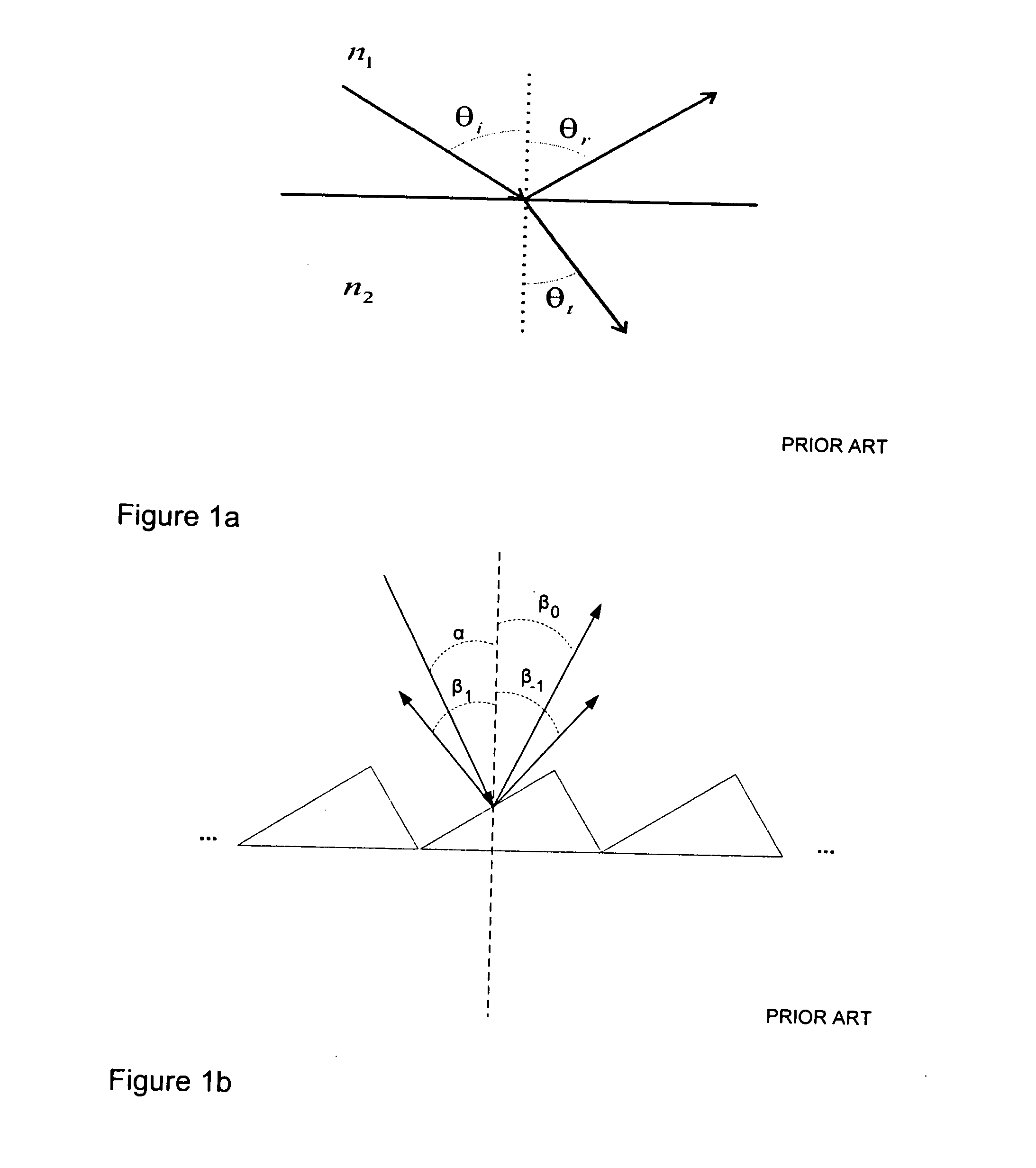
CROSS-REFERENCE TO RELATED APPLICATIONS[0001]This application claims priority to U.S. provisional patent application 60 / 855,362 filed 31 Oct. 2006, the entire contents of the disclosure of which is hereby incorporated by reference.FIELD OF THE INVENTION[0002]Generally the invention relates to optics. In particular the invention pertains to light outcoupling and directing structures utilizing the effect of diffractive gratings.BACKGROUND[0003]Diffractive grating structures are fine structures (cross-sectional profile e.g. 5 microns) of a surface that condition the passage of light based on physical optics including the diffraction effect. Many known ‘micro-prismatic’ structures are not true diffractive structures as they are relatively large (cross-sectional profile e.g. 50 microns), whereby altering the light passage is solely based on refraction effect therein, i.e. only the principles of geometric optics are applied.[0004]Generally refraction of light at the interface between two ...

Claims


Application Information

Patent Timeline
IPC IPC(8): G02B5/18
CPCG02B6/0036G02B6/0061G02B6/0038G02B5/1861G02B6/00G02B6/0001
Inventor RINKO, KARI
Owner MODILIS HLDG LLC
Why Eureka
Try Eureka