Eureka AIR delivers breakthrough ideas for toughest innovation challenges, trusted by R&D personnel around the world.

Memory row and column redundancy

Active Publication Date: 2008-09-18
SIEMENS PROD LIFECYCLE MANAGEMENT SOFTWARE INC
View PDF8 Cites 3 Cited by
  • Summary
  • Abstract
  • Description
  • Claims
  • Application Information

AI Technical Summary

Benefits of technology

[0008]In accordance with a first aspect of the invention, a memory includes: a redundant row-unit having one or more rows of memory cells; a plurality of memory cells arranged according to rows, wherein the rows are arranged into a plurality of row-units such that each row-unit has the same number of rows, and wherein the redundant row-unit includes the same number of rows; a plurality of repair memory cells corresponding on a one-to-one basis with the plurality of row-units, each repair memory cell operable to store a repair true or false value signal; and an X decoder for addressing the rows, the X decoder adapted to respond to an address for a row-unit having a repair memory cell storing the repair true signal by addressing a unit selected from the remaining row-units and the redundant row-unit, wherein each repair memory cell is adapted to store the repair true signal in response to an assertion of a set signal and an addressing of the corresponding row-unit.
[0009]In accordance w

Problems solved by technology

Despite advances in semiconductor process technology, integrated circuit memories may be manufactured with errors.
Because a just single bit error may render a memory unusable, manufacturers have implemented various techniques to repair memories in which memory cells have been identified as faulty.
If, however, a memory cell is faulty, a redundant memory component may be substituted for one of the non-redundant memory components such that the memory component including the faulty memory cell is no longer used.
Although each X decoder may thus identify whether a faulty row-unit exists, the X decoder must include a decoding portion to decode the contents of the bus, thereby occupying valuable die space.
Moreover, the routing of the necessary buses complicates design.

Method used


Image

  • Memory row and column redundancy
  • Memory row and column redundancy
  • Memory row and column redundancy

Examples


Embodiment Construction

[0018]Reference will now be made in detail to one or more embodiments of the invention. While the invention will be described with respect to these embodiments, it should be understood that the invention is not limited to any particular embodiment. On the contrary, the invention includes alternatives, modifications, and equivalents as may come within the spirit and scope of the appended claims. Furthermore, in the following description, numerous specific details are set forth to provide a thorough understanding of the invention. The invention may be practiced without some or all of these specific details. In other instances, well-known structures and principles of operation have not been described in detail to avoid obscuring the invention.

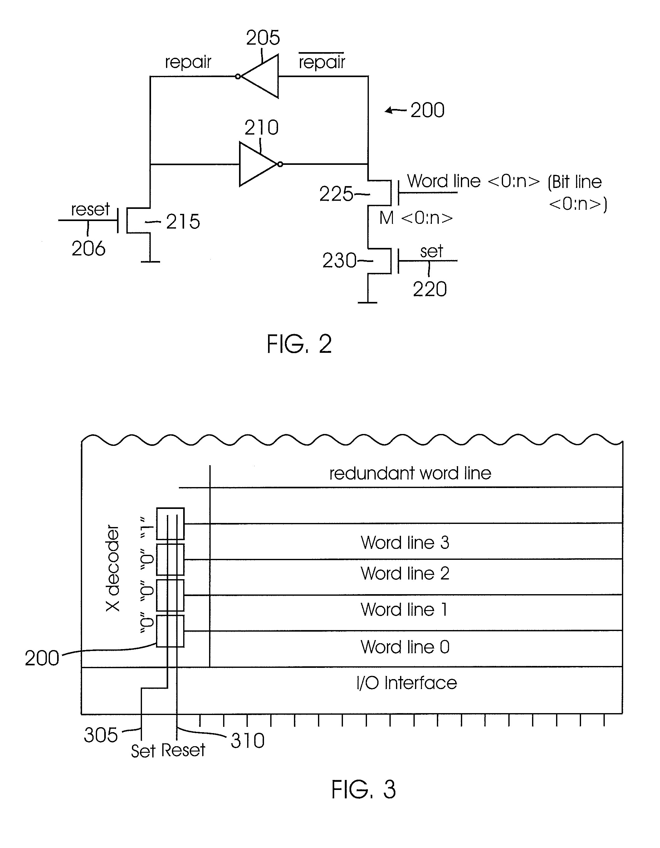
[0019]Turning now to FIG. 2, a row redundancy architecture is shown that eases the I / O resource demands and die area demands discussed earlier by storing the row redundancy identification information in binary storage cells such as repair memory c...


PUM


Abstract

In one embodiment, a memory includes a row and / or column redundancy architecture that uses binary cells to indicate whether a given row or column of memory cells is faulty. The binary cell is adapted to store a “repair true” signal in response to a conventional access to the corresponding row or column and also the assertion of a set signal.

Description

RELATED APPLICATION[0001]This application is a continuation of International Application No. PCT / US2006 / 32222, filed Aug. 16, 2006, which in turn claims the benefit of U.S. Provisional Application No. 60 / 370,738, filed Aug. 16, 2005, the contents of both applications being incorporated by reference in their entirety.BACKGROUND OF THE INVENTION[0002]The present invention relates to memory circuits, and more particularly to memory circuits with row and column redundancy.[0003]Despite advances in semiconductor process technology, integrated circuit memories may be manufactured with errors. Because a just single bit error may render a memory unusable, manufacturers have implemented various techniques to repair memories in which memory cells have been identified as faulty. For example, memories may include redundant rows or columns of memory cells. These redundant components are not used if the memory's non-redundant memory cells contain no manufacturing errors. If, however, a memory cel...

Claims


Application Information

Patent Timeline
IPC IPC(8): G11C7/00G11C8/00
CPCG11C29/789
Inventor AFGHAHI, MORTEZA CYRUSTERZIOGLU, ESINWINOGRAD, GIL I.
Owner SIEMENS PROD LIFECYCLE MANAGEMENT SOFTWARE INC
Why Eureka
Eureka Blog
Learn More