
Inkjet Solid Imaging System and Method for Solid Imaging

a solid imaging and inkjet technology, applied in the field of solid imaging, can solve the problems of product tackyness, limitation of the size of the objects that can be built, and number of drawbacks that have yet to be resolved, so as to reduce post-build processing requirements, without losing features or increasing exposure time

Inactive Publication Date: 2008-09-18
3D SYST INC
View PDF55 Cites 96 Cited by
  • Summary
  • Abstract
  • Description
  • Claims
  • Application Information

AI Technical Summary

Benefits of technology

[0010]The invention relates to solid imaging apparatus and methods for providing three-dimensional objects with greater efficiency. In some embodiments, the invention provides builds that require less processing after the build is completed, either in its green state or fully cured. The invention includes in selected embodiments, if desired, one or more of the added capabilities of producing builds in either batch or semi-continuous mode in a tack free or nearly tack free condition, fully curing the builds, and producing builds with equivalent or better feature detail and in larger sizes than presently available. The apparatus and method of the invention can be incorporated into downstream manufacturing processes.

Problems solved by technology

Despite the variety of devices and methods developed for solid imaging, a number of drawbacks have yet to be resolved.
Solid imaging devices produce “green” three-dimensional products, in which uncured build material wets the surface and causes the product to be tacky and to require cleaning prior to fully curing the product throughout the build.
Another drawback of many solid imaging devices is the limitation on the size of the objects that can be built.
For machines that use a laser as the radiation source for transformation of build material, the time required to build the object is directly related to the object's size because of limitations on the speed with which a laser can scan the surface of the cross-section.

Method used


Image

  • Inkjet Solid Imaging System and Method for Solid Imaging
  • Inkjet Solid Imaging System and Method for Solid Imaging
  • Inkjet Solid Imaging System and Method for Solid Imaging

Examples


Embodiment Construction

[0064]The invention can be best understood with reference to the specific embodiments that are illustrated in the drawings and the variations described herein below. While the invention will be so described, it should be recognized that the invention is not intended to be limited to the embodiments illustrated in the drawings. On the contrary, the invention includes all alternatives, modifications, and equivalents that may be included within the spirit and scope of the invention as defined by the appended claims.

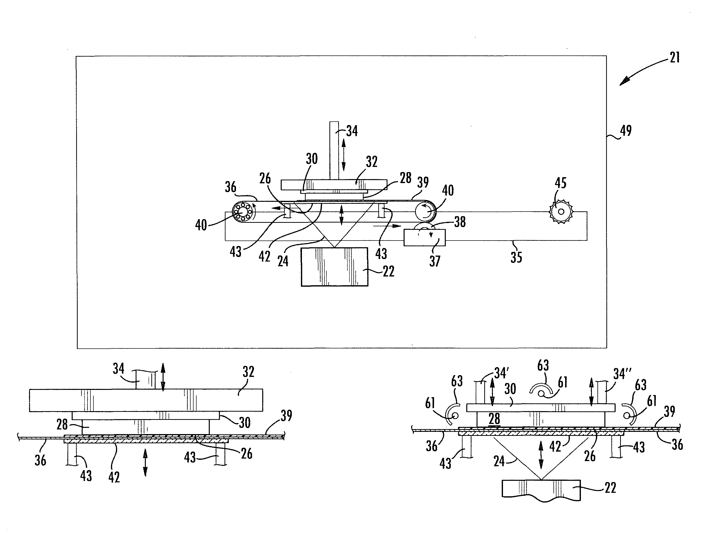
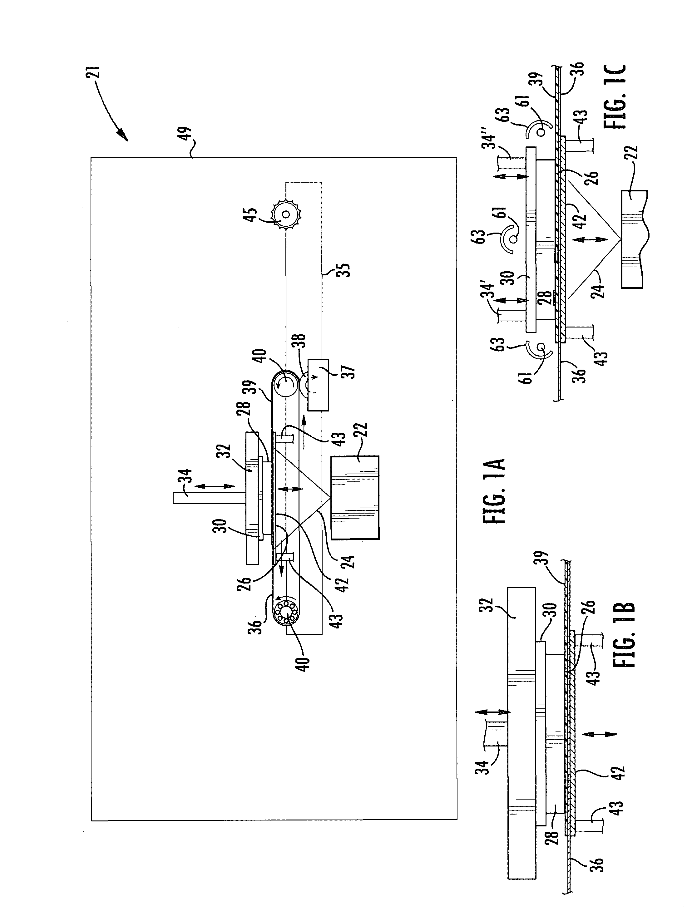
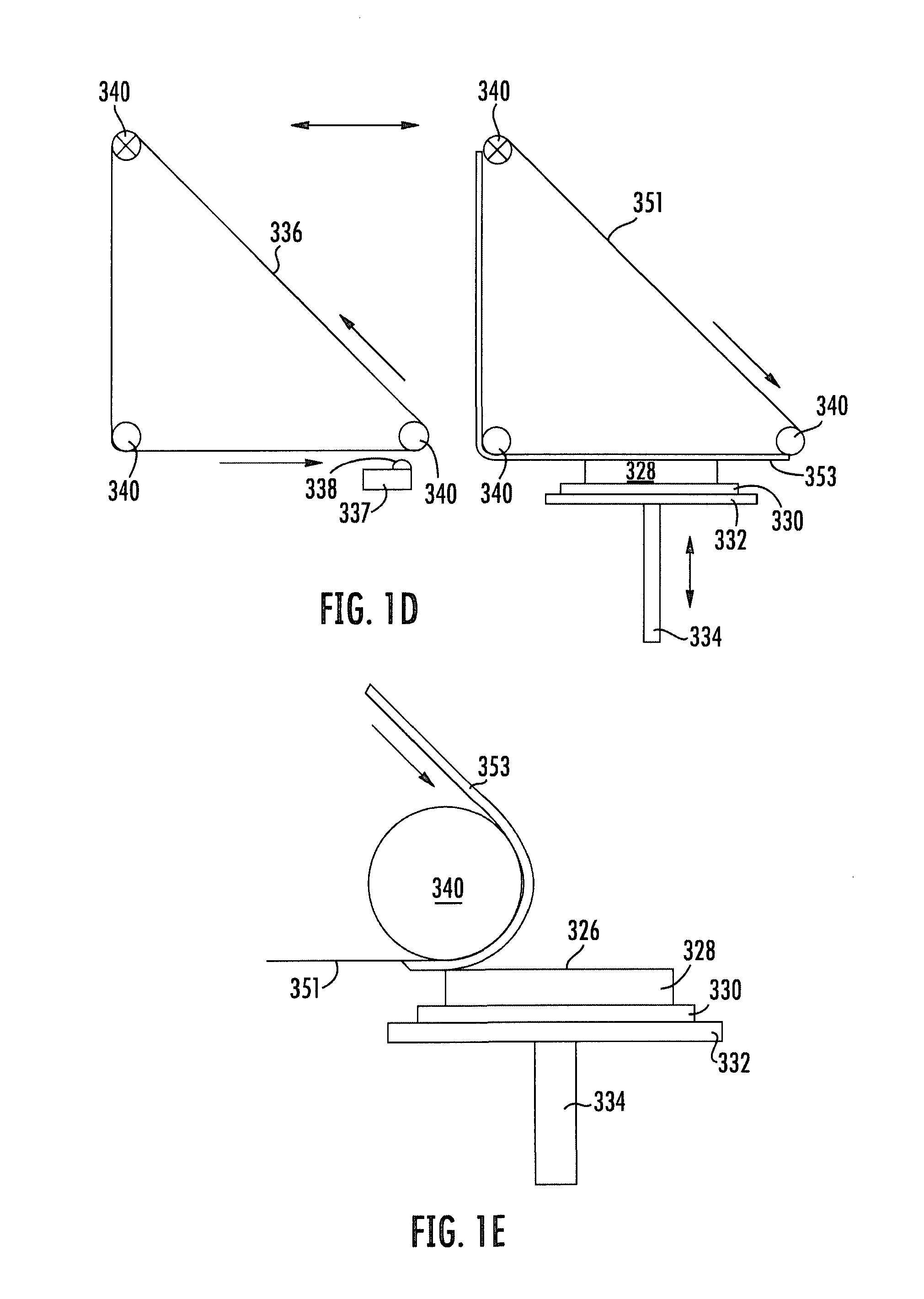
[0065]FIG. 1A shows generally at 21 a schematic longitudinal plan view of one embodiment of a flexible transport solid imaging device of the invention during the coating and imaging stage of its operation. FIG. 1B illustrates features of FIG. 1A enlarged for detail. A radiation source 22 provides focused solid imaging radiation 24 that is projected onto the build material-wetted surface 26 of a build 28 to cure selected portions of the fresh build material layer in an image ...


PUM

PropertyMeasurementUnit
Timeaaaaaaaaaa
Areaaaaaaaaaaa
Surfaceaaaaaaaaaa

Abstract

Solid imaging apparatus and methods for use are disclosed that reduce the amount of uncured solid imaging build material remaining on a completed build object following the completion of the solid imaging build process. The amount of uncured build material is reduced through the use of either an uncoating web that removes excess build material from the build object during the course of the building process or an ink jet source of build material that uses only as much build material as is necessary for the fabrication of the build part. Also disclosed is an imager assembly for use with such a solid imaging apparatus that incorporates two or more individual imagers in an array and accounts for variations in the intensity and alignment of adjacent imagers. The apparatus can be modified for semi-continuous operation and for integrating into a manufacturing operation, if desired.

Description

CROSS-REFERENCE TO RELATED APPLICATIONS[0001]This application claims priority from Non-provisional application Ser. No. 11 / 096,748 filed Apr. 1, 2005 for “Edge Smoothness with Low Resolution Projected Images for Use in Solid Imaging;” Non-provisional application Ser. No. 11 / 121,348 filed May 3, 2005 for “Bubble-free Cross-sections for Use in Solid Imaging;” Non-provisional application Ser. No. 11 / 375,917 filed Mar. 15, 2006 for “Bubble-free Cross-sections for Use in Solid Imaging;” Non-provisional application Ser. No. 11 / 468,090 filed Aug. 29, 2006 for “Improved Wall Smoothness;” Provisional Application Ser. No. 60 / 885,254 filed Jan. 17, 2007 for “Coat and Un-coat Flex Transport System; Provisional Application Ser. No. 60 / 885,257 filed Jan. 17, 2007 for “Solid Imaging Apparatus and Method Including: Cartridge for Solid Imaging Apparatus; Method for Conveying Build Material Layer-By-Layer; Elevator for Tilting Solid Image Build Platform for Reducing Air Entrainment and for Consistent...

Claims


Application Information

Patent Timeline
IPC IPC(8): G03G15/04
CPCB29C67/0055B33Y10/00B33Y30/00B29C64/141B29C64/223B29C64/106
Inventor HULL, CHARLES W.SPERRY, CHARLES R.
Owner 3D SYST INC
Learn More