Imbalanced transmission combining at radio base station

Inactive Publication Date: 2008-09-18
HIGHBRIDGE PRINCIPAL STRATEGIES LLC AS COLLATERAL AGENT
View PDF6 Cites 6 Cited by
  • Summary
  • Abstract
  • Description
  • Claims
  • Application Information

AI Technical Summary

Benefits of technology

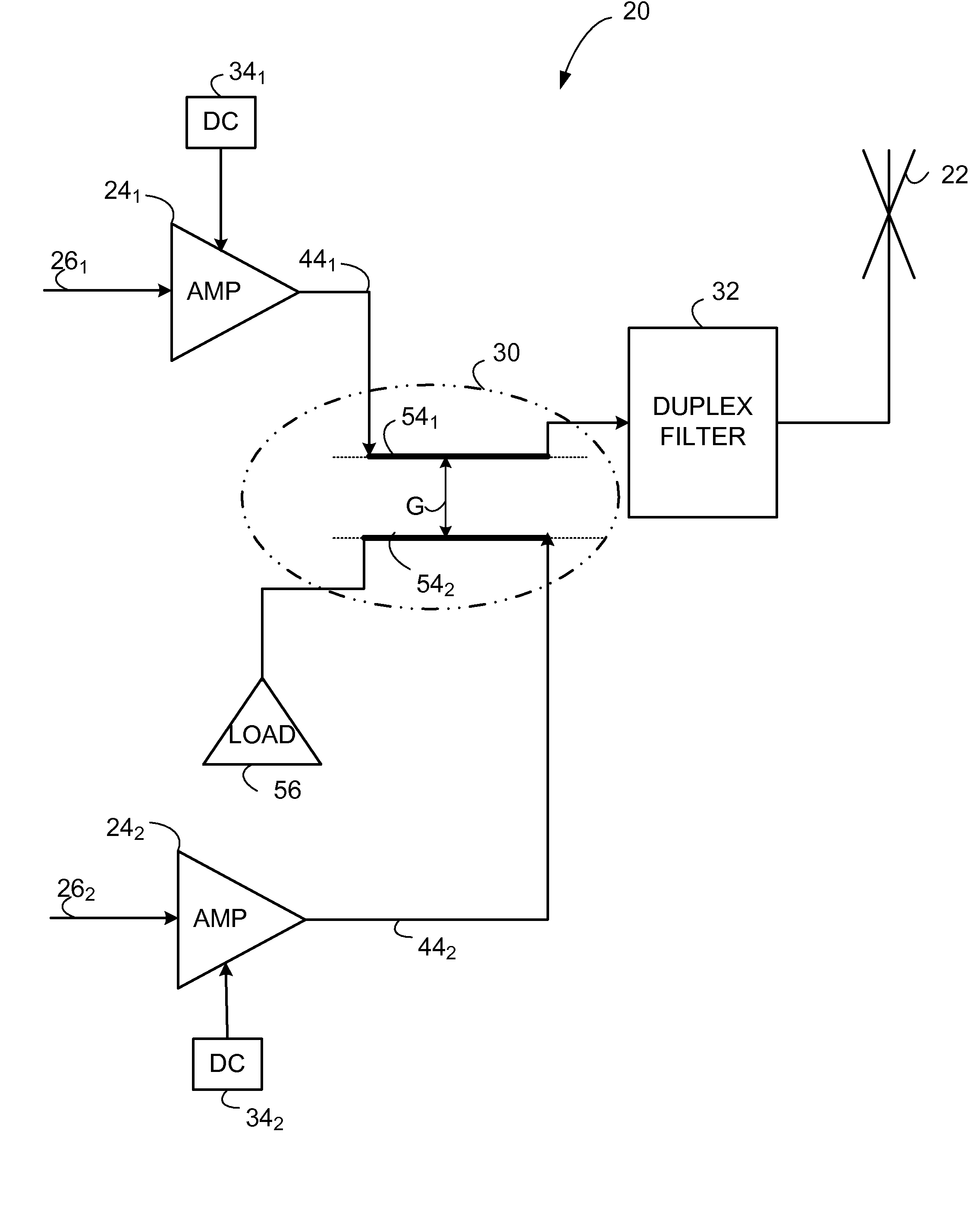
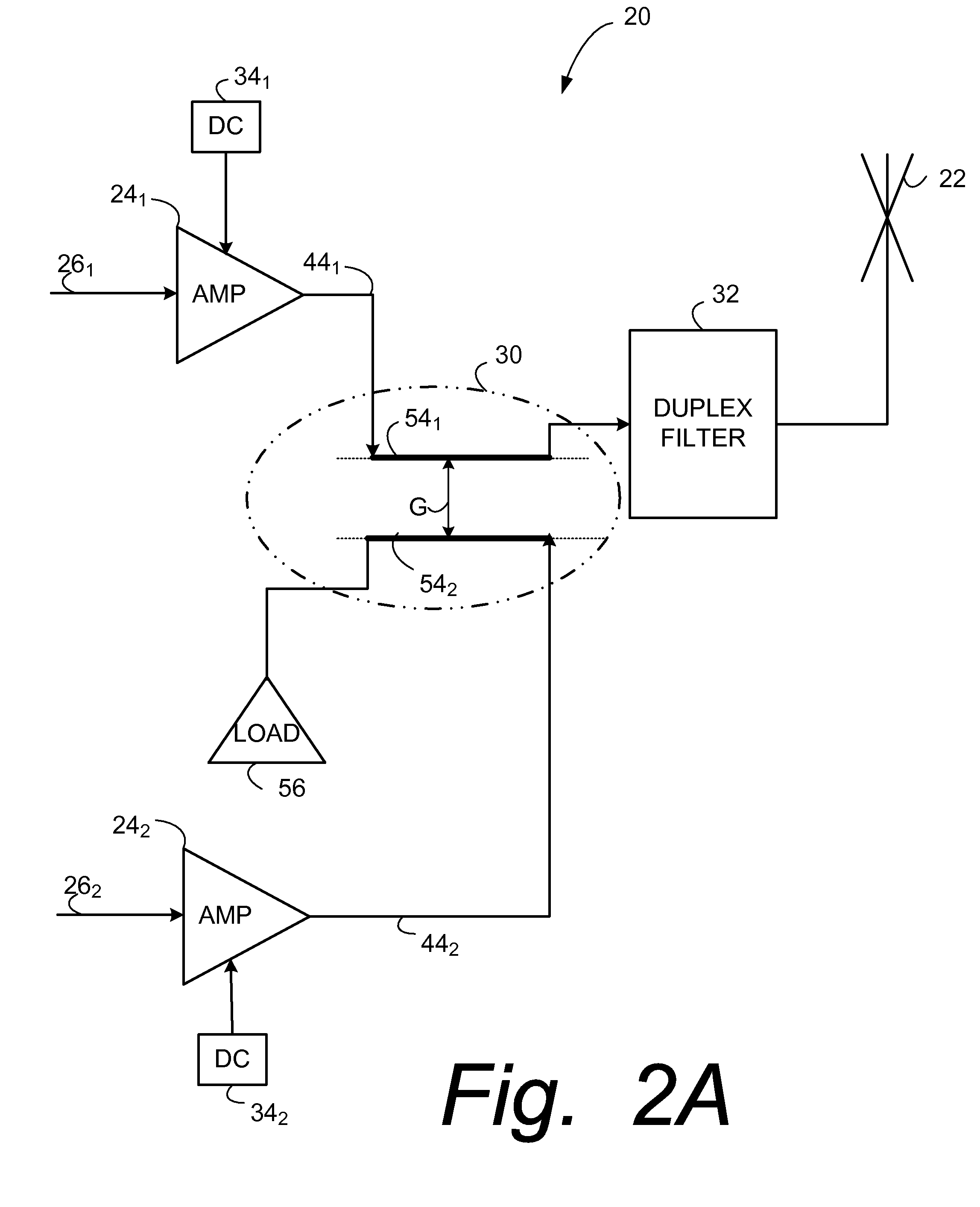
[0017]A coupling medium is preferably positioned, situated, or accommodated between first coupling element and second coupling element. One or more attributes of the coupling medium are chosen or changed to impart the power imbalance of the imbalanced combiner, e.g., the power imbalance between the first power level of the first carrier signal and the second power level of the second carrier signal. The one or more attributes of the coupling medium chosen to impart the power imbalance can be, for example, characteristic, composition or configuration (e.g., shape or dimension) of the coupling medium. In one example embodiment the coupling element happens to fluid, such as air, for example. In another example embodiment the coupling medium is either fluidic, solid, or semi-solid having one or more attributes selected to achieve the desired power imbalance.
[0018]The second coupler element is spaced apart from the first coupler element by a gap. In some example embodiments, the power imbalance in the power imbalanced combined signal is related to a magnitude of the gap. Stated differently, a power ratio of the first power level to the second power level is related to a magnitude of the gap (e.g., an example of configuration of the coupling medium). Typically the power ratio is in a range from about 2:1 to about 10:1. In other examp

Problems solved by technology

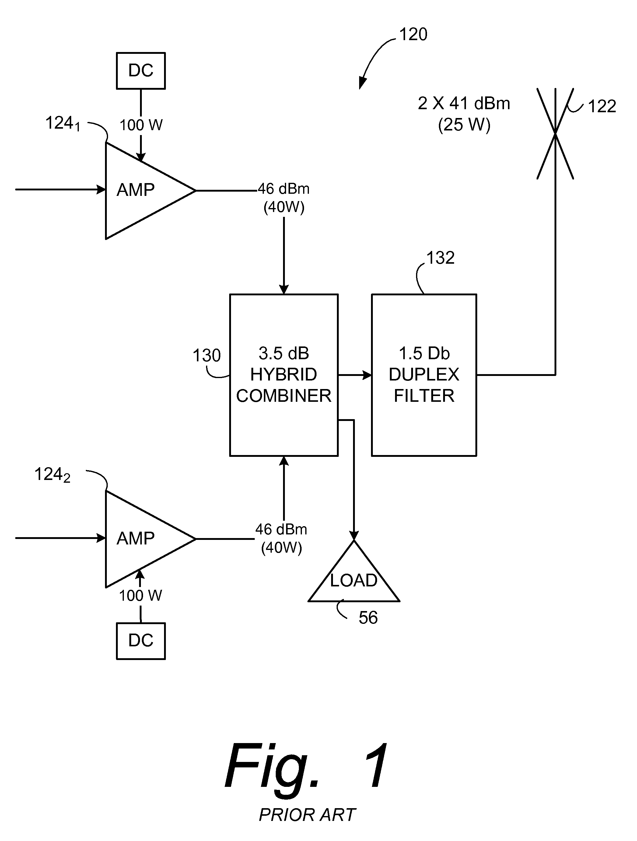
The power imbalanced combined signal has a significant power imbalance between a first power level

Method used


Image

  • Imbalanced transmission combining at radio base station
  • Imbalanced transmission combining at radio base station
  • Imbalanced transmission combining at radio base station

Examples


Example

[0034]In the following description, for purposes of explanation and not limitation, specific details are set forth such as particular architectures, interfaces, techniques, etc. in order to provide a thorough understanding of the present invention. However, it will be apparent to those skilled in the art that the present invention may be practiced in other embodiments that depart from these specific details. That is, those skilled in the art will be able to devise various arrangements which, although not explicitly described or shown herein, embody the principles of the invention and are included within its spirit and scope. In some instances, detailed descriptions of well-known devices, circuits, and methods are omitted so as not to obscure the description of the present invention with unnecessary detail. All statements herein reciting principles, aspects, and embodiments of the invention, as well as specific examples thereof, are intended to encompass both structural and functiona...


PUM


Abstract

A radio base station (20) comprises an antenna (22); a first power amplifier (241) configured to receive a first carrier signal; a second power amplifier (242) configured to receive a second carrier signal; and an imbalanced combiner (30). The imbalanced combiner (30) is configured to apply a power imbalanced combined signal to the antenna. The power imbalanced combined signal has a power imbalance between a first power level of the first carrier signal and a second power level of the second carrier signal as transmitted from the antenna (22).

Description

BACKGROUND[0001]I. Technical Field[0002]This invention pertains to telecommunications, and particularly to the construction and operation of base stations which communicate with wireless terminals over an air interface.[0003]II. Related Art and Other Considerations[0004]In a typical cellular radio system, wireless user equipment units (UEs) communicate via a radio access network (RAN) to one or more core networks. The user equipment units (UEs) can be mobile stations such as mobile telephones (“cellular” telephones) and laptops with mobile termination, and thus can be, for example, portable, pocket, hand-held, computer-included, or car-mounted mobile devices which communicate voice and / or data with radio access network. Alternatively, the wireless user equipment units can be fixed wireless devices, e.g., fixed cellular devices / terminals which are part of a wireless local loop or the like,[0005]The radio access network (RAN) covers a geographical area which is divided into cell areas...

Claims


Application Information

Patent Timeline
IPC IPC(8): H04B1/02
CPCH01P5/04H04B1/0483H01P5/185H01P5/16
Inventor LINDSKOG, MATS KRISTIAN
Owner HIGHBRIDGE PRINCIPAL STRATEGIES LLC AS COLLATERAL AGENT
Why Eureka
Try Eureka