Cervical support system

a cervical spine and support system technology, applied in the field of cervical spine support devices, can solve the problems of significant risks to the vertebral artery, the location and angle of the screw entry and the screw insertion is not well suited for screw insertion, and the sub-axial cervical spine fixation is a stabilization suppor

Inactive Publication Date: 2008-09-18
SHAMIE ARYA NICK
View PDF16 Cites 23 Cited by
  • Summary
  • Abstract
  • Description
  • Claims
  • Application Information

AI Technical Summary

Benefits of technology

[0007]The present invention relates to an apparatus for connecting between an upper cervical vertebrae and a cervical fixation network that includes a screw having a portion with a tapered shaft with a helical rim for rotationally entering and gripping the upper cervical vertebr...

Problems solved by technology

One drawback to systems providing sub-axial cervical spine fixation is stabilization support for certain upper vertebrae, referred to as the C1 and C2 vertebrae.
Until recently, common techniques for the placement of screws in the C2 for fixation to a fixation network such as a lateral mass screw and rod fixation system resulted i...

Method used


Image

  • Cervical support system
  • Cervical support system
  • Cervical support system

Examples


Embodiment Construction

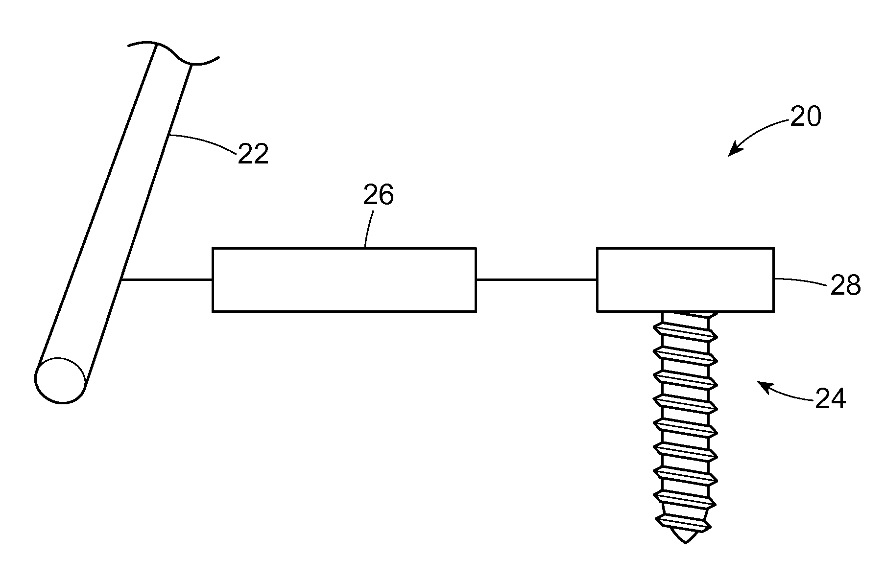
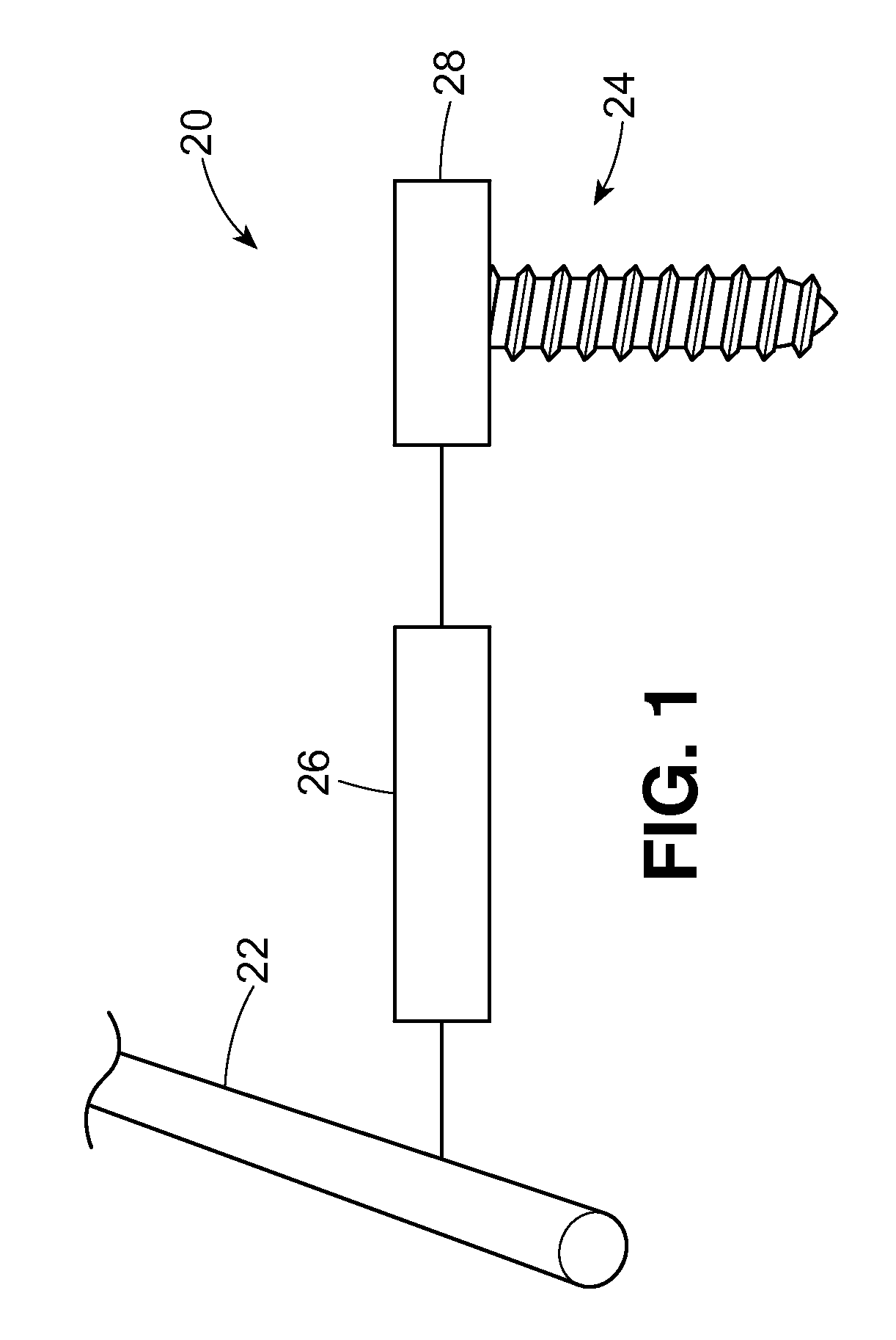
[0028]With reference to the drawings for purposes of illustration, an improved system 20 is provided for fixation of the C2 to a rigid cervical fixation network 22 such as, but not limited to, a screw and rod system, using a screw or post 24. Advantageously, a low profile bridge 26 is provided between the rigid cervical fixation network 22 and the screw 24. Furthermore, a connector 28 is included that facilitates connection of the screw 24 to the bridge 26. Presently the screw 24, connector 28 and the bridge 26 may be made from any material or material combination, without limitation, suitable for insertion into a living body. For example, but not by means of limitation, the materials may include stainless steel, a cobalt / chrome alloy, titanium or any alloy combination thereof. Presently, titanium alloy materials are preferred in the medical community and therefore, for that reason, would be preferred in this invention. However, changes in materials preferred by the medical communit...


PUM


Abstract

An apparatus for connecting between an upper cervical vertebrae and a cervical fixation network that includes a screw for rotationally entering and gripping the upper cervical vertebrae. A bridge is configured to route between the cervical fixation network and the screw. A connector holding the screw and bridge together includes a portion of the screw and the bridge that is configured differently for a complementary, low profile engagement of the bridge and screw in which varying configurations of the connector and bridge, either alone, or in combination, are envisioned.

Description

CROSS-REFERENCE TO RELATED APPLICATION(S)[0001]This application claims the benefit of U.S. Provisional Application Ser. No. 60 / 906,272 filed on Mar. 12, 2007, which is incorporated herein by reference.FIELD OF THE INVENTION[0002]This invention relates generally to cervical support devices, and, more particularly, to a system for providing low profile cervical support to the vertebrae.BACKGROUND OF THE INVENTION[0003]With the advent of modern surgical techniques, methods and systems using rigid cervical support devices have been developed to manage instability of the upper cervical spine in a human body. Such methods and systems have been implemented successfully in patients with cervical disorders requiring stabilization resulting in improved spinal support for the neck and head as well as improvements in relief from pain resulting from such instability.[0004]One drawback to systems providing sub-axial cervical spine fixation is stabilization support for certain upper vertebrae, ref...

Claims


Application Information

Patent Timeline
IPC IPC(8): A61B17/58A61B17/56A61B17/08
CPCA61B17/7058A61B17/7041
Inventor SHAMIE, ARYA NICK
Owner SHAMIE ARYA NICK
Why Eureka
Try Eureka