Composite Prosthetic Foot

a prosthetic foot and composite technology, applied in the field of prosthetic feet, can solve the problems of unsuitable for foot replacement, unsuitable for hollow shape hollow shape manufacturing with complex geometry, high cost and slow autoclave process, etc., to achieve high torsional and radial tensile load, avoid large interlaminar tensile or shear stress, and effectively in the foot structure

Inactive Publication Date: 2008-09-18
CLOSEDMOLD COMPOSITES
View PDF31 Cites 37 Cited by
  • Summary
  • Abstract
  • Description
  • Claims
  • Application Information

AI Technical Summary

Benefits of technology

[0015]It is an additional object of the invention to produce a prosthetic foot of hollow composite tubing in a fashion allowing a wide range of geometries to be utilized effectively in foot structure,...

Problems solved by technology

However, the performance characteristics desired by each amputee vary substantially and a tunable dynamic response prosthetic foot design providing high and low dynamic response capabilities is desired.
The result is that most dynamic response prostheses are of a high profile design and not really suitable for foot replacement at the ankle.
The autoclave process is expensive and slow and is unsuited for the manufacture of hollow shapes with a complex geometry.
The material near the mid-plane of this planar structure are relatively inefficient, contributing weight but not capable of storing signifi...

Method used


Image

  • Composite Prosthetic Foot
  • Composite Prosthetic Foot
  • Composite Prosthetic Foot

Examples


Embodiment Construction

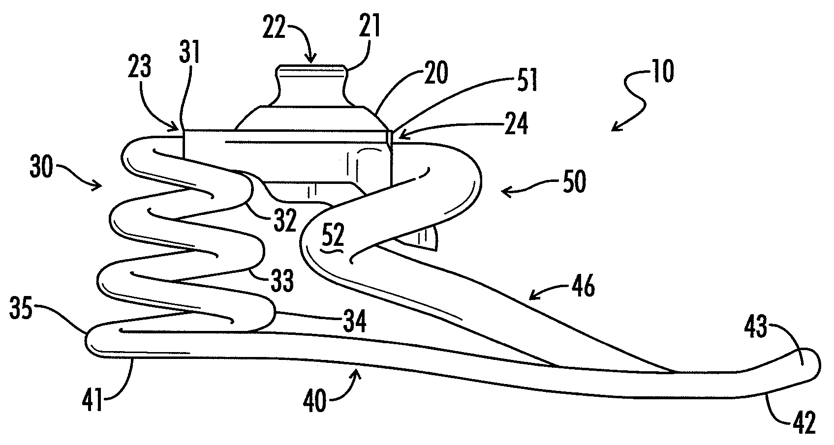
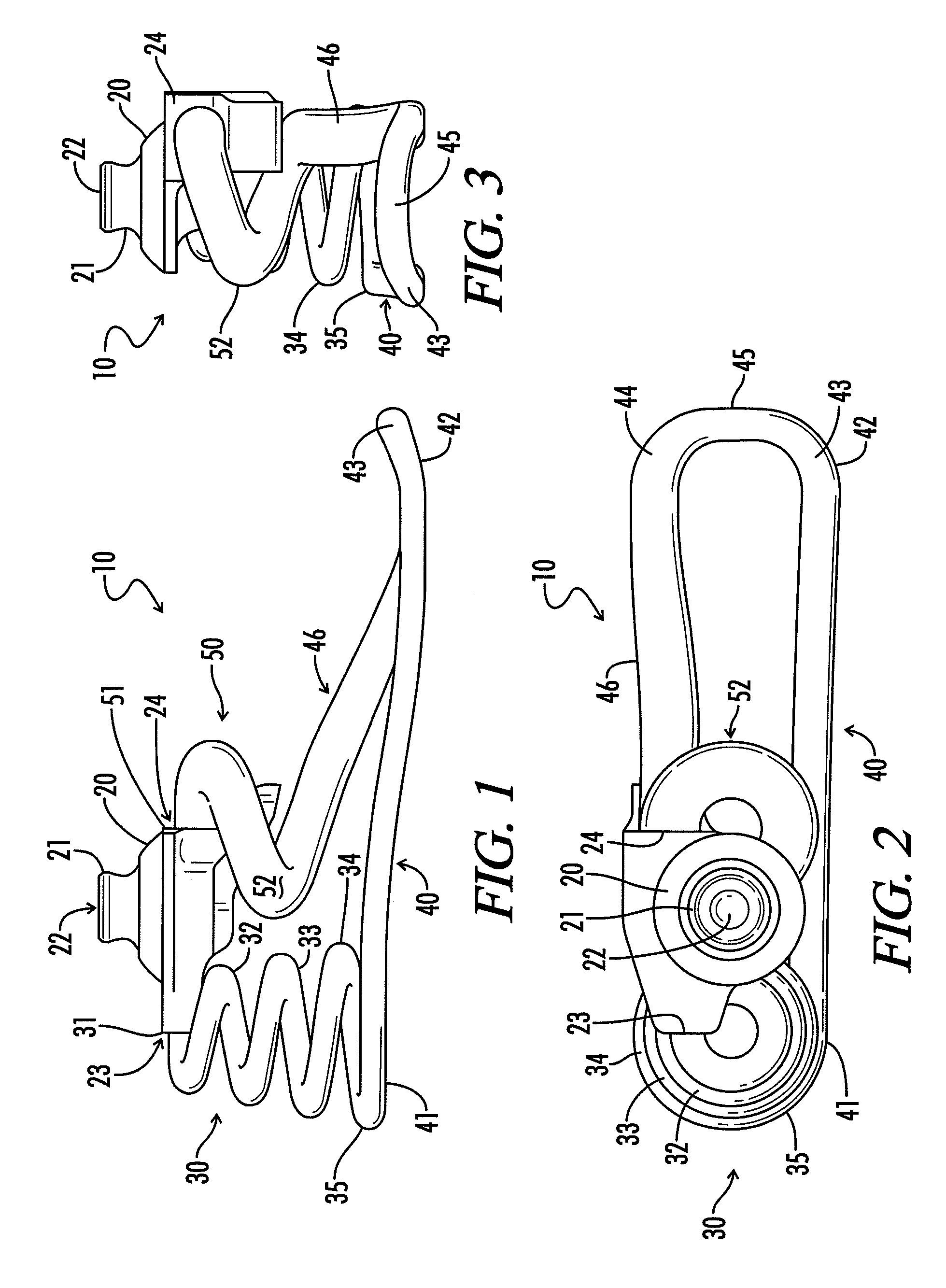
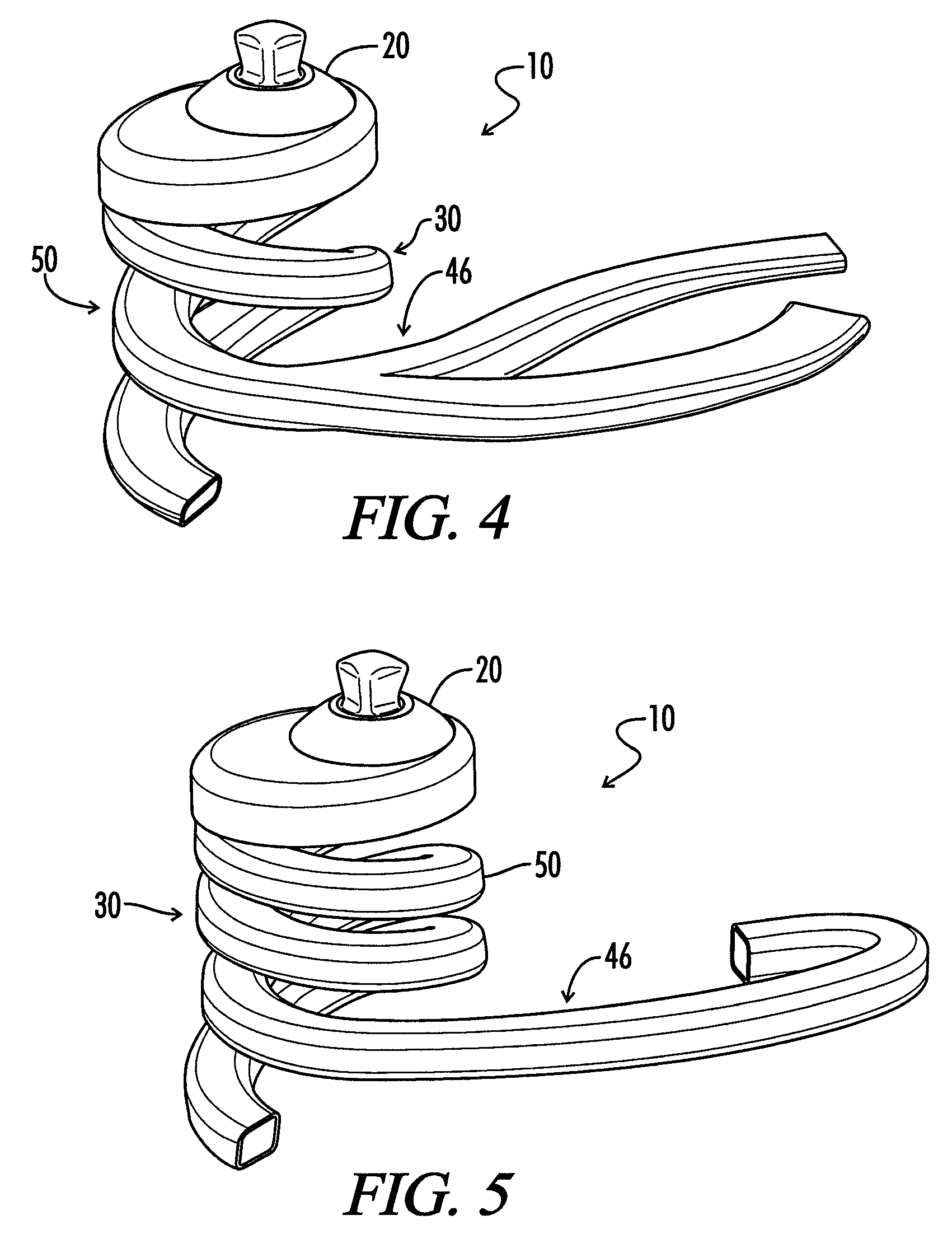
[0031]Referring now to the drawings wherein like numbered reference numerals designate corresponding parts throughout the several views, according to the embodiments of the invention illustrated in the non-limiting FIGS. 1 through 11. The principal elements of prosthetic foot 10 comprise a mounting element such as an ankle plate 20, a heel spring 30, a keel portion formed of a forespring 50 and an arch member 46, and a lateral longitudinal support member 40. The ankle plate 20 has an upward facing attachment point defined by a housing such as the convex hemispherical surface beneath an inverted pyramid 21 which is received by a mating component attached to the end of a pylon or other attachment extending downward from amputee's stump. These mating surfaces allow for static multiaxial alignment of the foot with the remainder of the prosthesis and the limb. The aperture 22 is solely provided for weight reduction. There is a rear attachment point 23 for connection with heel spring 30 a...


PUM

PropertyMeasurementUnit
Angleaaaaaaaaaa
Angleaaaaaaaaaa
Piezoelectricityaaaaaaaaaa

Abstract

A prosthetic foot is provided with an ankle plate for attachment to a lower leg prosthesis and supporting a composite frame having a hollow composite biasing structure, preferably in the form of a generally helical spring curved about a vertical axis.

Description

[0001]The present application claims priority to the Mar. 13, 2007 filing date of U.S. provisional patent application, Ser. No. 60 / 906,687.FIELD OF THE INVENTION[0002]The present invention relates to a prosthetic foot and specifically to a prosthetic foot formed of composite tubing.BACKGROUND OF THE INVENTION[0003]Prostheses for amputated feet have been used since the times of ancient civilization. However, over time there have been numerous refinements in medicine, surgery, technology and prosthetic science resulting in the development of many designs of prosthetic feet. These feet can generally be divided into five categories:[0004]SACH foot, an acronym for Solid Ankle Cushion Heel, this is a simple design that is relatively inexpensive, durable, and can be made in lightweight configurations.[0005]SAFE FOOT—Solid Ankle Flexible Endoskeleton, this foot is more flexible than the SACH foot by allowing for a smooth rollover while walking and is sometimes called a flexible keel foot.[0...

Claims


Application Information

Patent Timeline
IPC IPC(8): A61F2/66
CPCA61F2/66B29L2031/7742A61F2002/5053A61F2002/5055A61F2002/5056A61F2002/5073A61F2002/5075A61F2002/6621A61F2002/6642A61F2002/665A61F2002/6664A61F2002/6678A61F2002/6685A61F2002/6692A61F2220/0033B29C33/505B29C70/202B29C70/222B29C70/46B29L2031/774A61F2002/30359
Inventor NELSON, RONALD HARRYCOOP, BRIAN T.STARK, GERALDBUCK, DANIEL
Owner CLOSEDMOLD COMPOSITES
Why Eureka
Try Eureka