Control of equipment using remote display

a remote display and control technology, applied in the direction of program control, instruments, unauthorized memory use protection, etc., can solve the problems of conventional deadman switch providing no method of identifying the operator, and conventional equipment control is often susceptible to jamming or locking

Inactive Publication Date: 2008-09-18
DEADMAN TECH
View PDF58 Cites 103 Cited by
  • Summary
  • Abstract
  • Description
  • Claims
  • Application Information

AI Technical Summary

Benefits of technology

[0007]Examples of the present invention allow an operator to monitor operational parameters of equipment, and to provide authorization for using the equipment, while allowing the operator to move around in the vicinity of the equipment.

Problems solved by technology

However, a conventional deadman switch provides no method of identifying the operator and so may be used by any person, even those not authorized or trained to use the equipment.
Also, conventional equipment controls are often susceptible to jamming or locking in an operating position.

Method used


Image

  • Control of equipment using remote display
  • Control of equipment using remote display
  • Control of equipment using remote display

Examples


Embodiment Construction

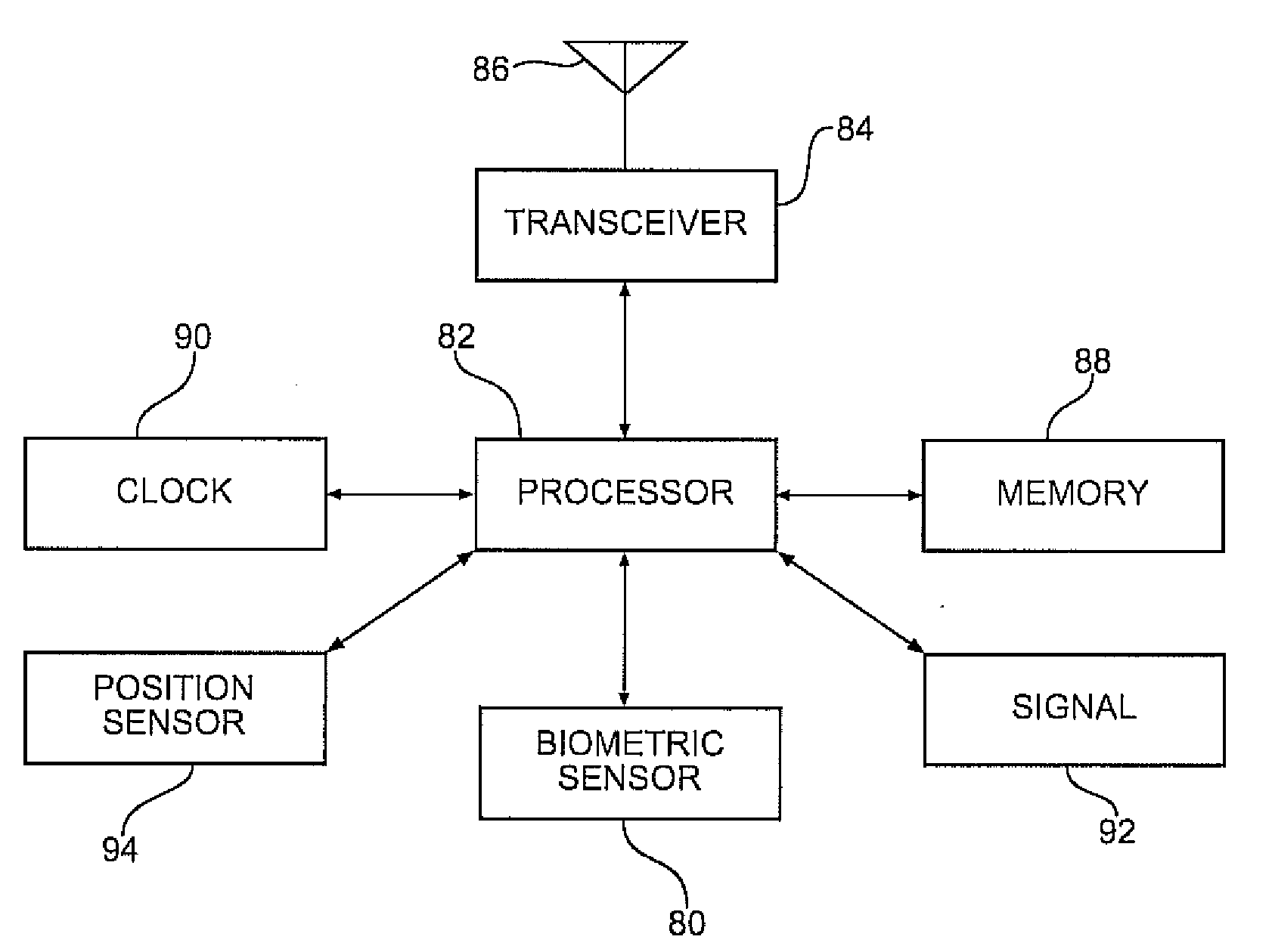
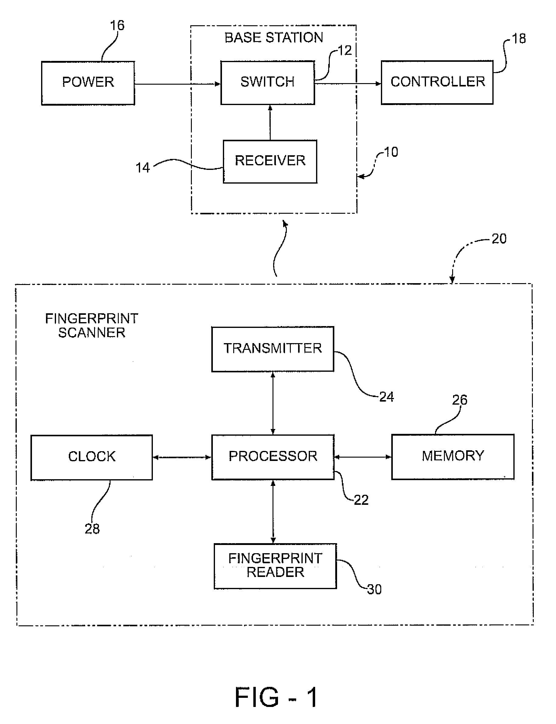
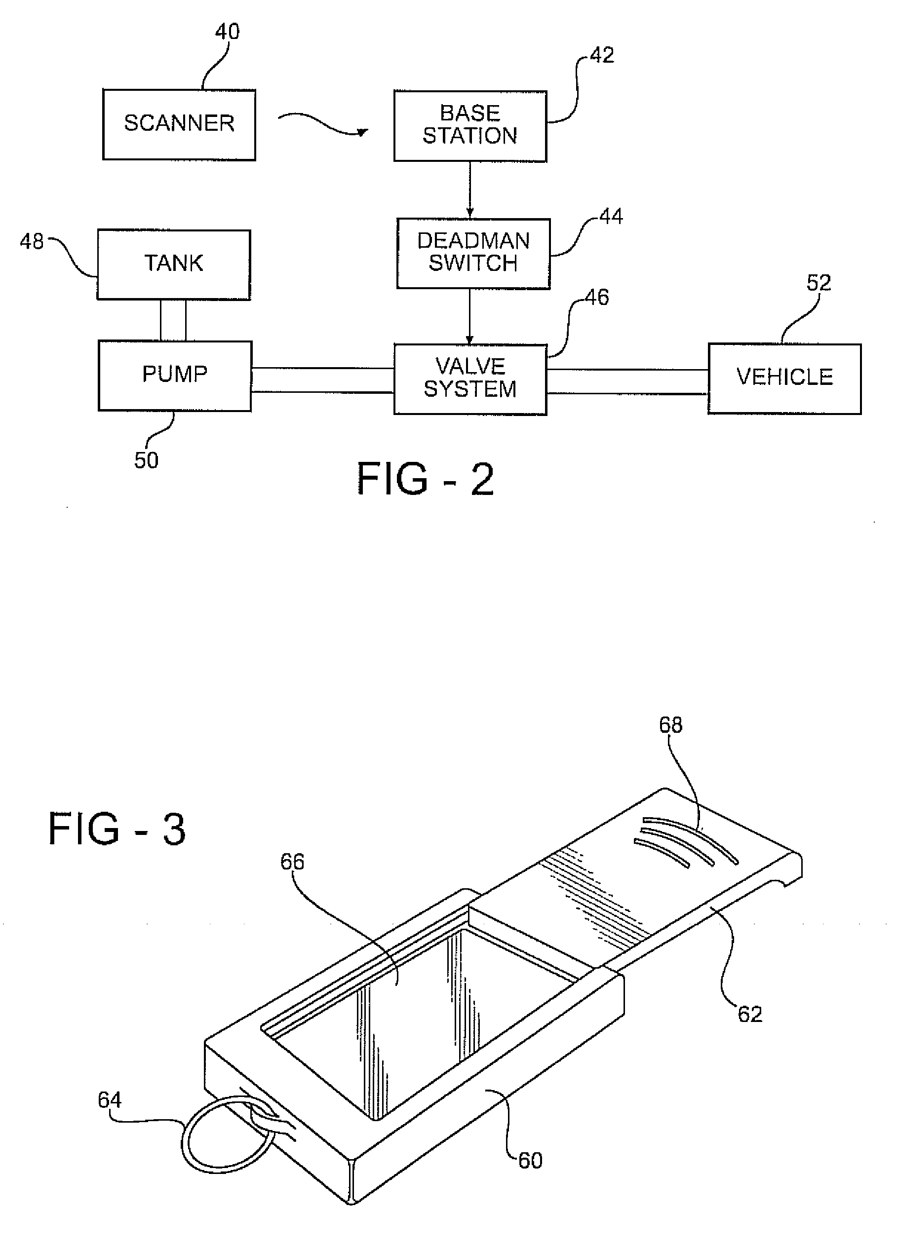
[0021]Examples of the present invention include a display unit having a cradle to receive a biometric scanner. In a representative example, the display unit includes a housing, a cradle for the biometric scanner in the form of a recess in the housing adapted to receive the biometric scanner, an electrical interface within the recess allowing electrical communication between the biometric scanner and the display unit, and a display, for example a liquid crystal display (LCD), light emitting display, or other electronic display. The display may be used to show operational parameters, transmission parameters such as transmitted or received signal strength, internal battery status, or other data. Operational parameters may include fuel flow data in gallons or liters (for fueling operations, such as fuel delivered and / or remaining to be delivered), operational duration, time to completion, and the like. Operational parameters may displayed numerically, as a fraction of a total (such as p...


PUM


Abstract

An example display unit for facilitating operation of equipment includes a housing, an electronic display supported by the housing, and an electronic circuit located within the housing. The display unit may include one or more data receivers, such as a wireless receiver and/or an electrical interface. A biometric scanner, including a biometric sensor and proving an authorization signal when an authorized biometric input is detected by the biometric sensor, may be configured to electrically (and optionally mechanically) interconnect to the display unit. The example display unit receives an authorization status for operation of the equipment from the biometric scanner, and displays the authorization status and operational parameters relating to equipment use on the electronic display.

Description

REFERENCE TO RELATED APPLICATION[0001]This application claims priority from U.S. Provisional Patent Application Ser. No. 60 / 892,312, filed Mar. 1, 2007, the entire content of which is incorporated herein by reference.FIELD OF THE INVENTION[0002]The invention relates to methods and apparatus for operating equipment, including methods and apparatus for allowing operation of equipment by authorized persons.BACKGROUND OF THE INVENTION[0003]Under typical aviation regulations, a deadman switch should be used when performing any pressure fueling or tender filling operation. Deadman switches are designed to safeguard against circumstances or situations that may delay the suspension of fuel flow. Preferably, a deadman switch should not be jammed or bypassed during any fuel transfer operation. Deadman switch types include the electric deadman switch, pneumatic deadman switch (sometimes called an air deadman switch), and combination air / pneumatic types. The deadman switch is actuated, for exam...

Claims


Application Information

Patent Timeline
Patent Type & Authority Applications(United States)
IPC IPC(8): G06F21/00
CPCG06F21/32
Inventor MILLER, BRIAN S.VAUGHAN, JACKLEDRIERE, OSCAR A.DISIMONE, GINO
Owner DEADMAN TECH
Why Eureka
Try Eureka