Rocking switch unit

a switch unit and rocking technology, applied in the direction of tumbler/rocker switch details, tumbler/rocker switch details, contact mechanisms, etc., can solve the problems of difficult to ensure the compatibility of pressing the tactile switch, the difficulty of rocking switch knobs to press the switch surfaces vertically, and the long distance between the rocking switch knob and the tactile switch, so as to ensure the operation of the switch knob and the operation feeling, reduce the number of components, and improve the effect of assembly efficiency

Inactive Publication Date: 2008-09-25
DENSO CORP
View PDF9 Cites 9 Cited by
  • Summary
  • Abstract
  • Description
  • Claims
  • Application Information

AI Technical Summary

Benefits of technology

[0018]In the present rocking switch unit, when one of the rocking end portions is pressed, the switch-pressing portions are rotatable with respect to the middle rocking section. Thus, the switch-pressing portions can be linearly movable toward the tactile switches. As a result, switch surfaces of the tactile switches are pressed vertically, and thereby an operability of the switch knob and an operation feeling can be ensured. Furthermore,...

Problems solved by technology

Thus, when a distance between the rocking fulcrum and the switch surfaces of the tactile switches increases, the rocking switch knob is difficult to press the switches surfaces vertically.
However, in the seesaw switch that is attached to an operating panel for operating the electronic apparatus installed in the vehicle, a distance between the rocking switch knob and the tactile switches becomes long, for example, due to ...

Method used


Image

  • Rocking switch unit
  • Rocking switch unit
  • Rocking switch unit

Examples


first embodiment

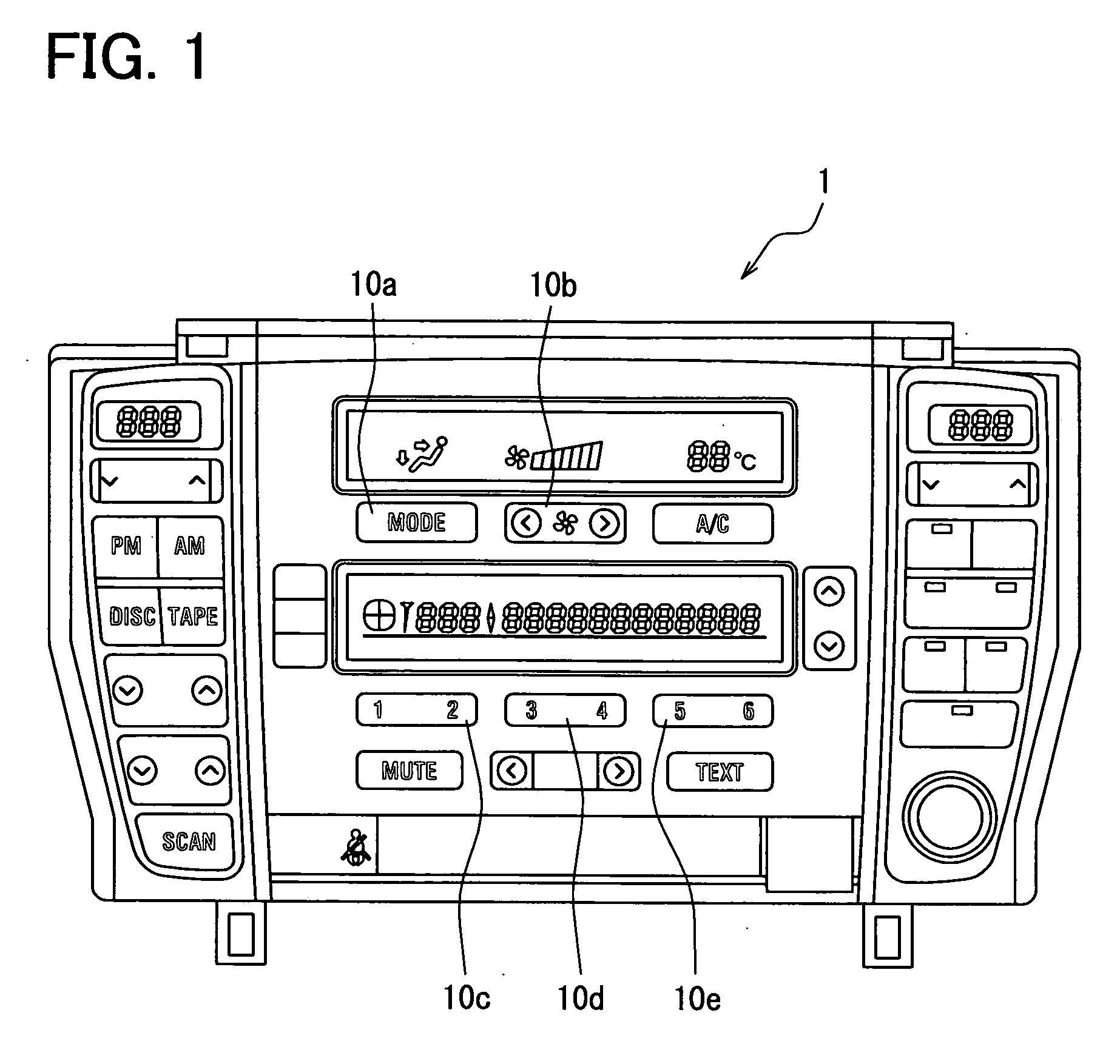
[0044]A rocking switch unit 10 according to a first embodiment of the invention can be used as first to fifth rocking switch units 10a-10e disposed at a front panel 1 shown in FIG. 1. The first rocking switch unit 10a is provided for switching an outlet vent of conditioned air. The second rocking switch unit 10b is provided for changing a flow amount of conditioned air. The third to fifth rocking switch units 10c-10e are provided for selecting music of an audio device. The front panel 1 further includes a display and other switch units for controlling an on-board electronic apparatus including an air-conditioning device and the audio device. The on-board electronic apparatus can be controlled by operating the switch units including the first to fifth rocking switch units 10a-10e. An exemplary configuration of the rocking switch unit 10 including the first to fifth rocking switch units 10a-10e will now be described with reference to FIGS. 1-8.

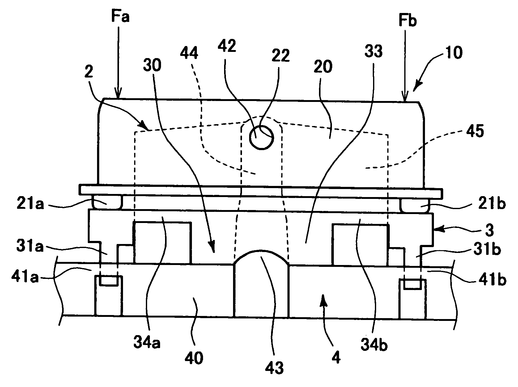
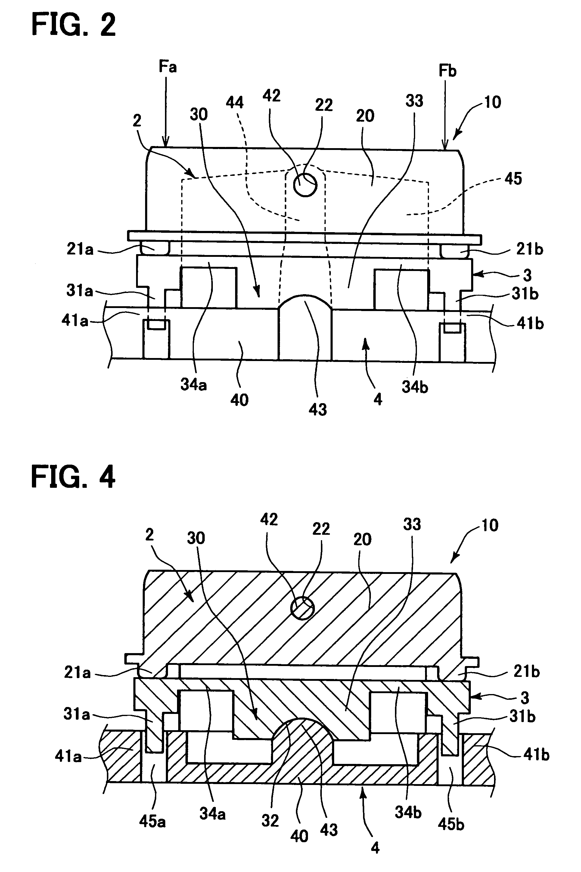
[0045]The rocking switch unit 10 includes...

second embodiment

[0064]In the rocking switch unit 10 according to the first embodiment, the rocking poles 34a and 34b of the middle rocking section 30 can deform elastically. Thereby, the switch-pressing portions 31a and 31b can move linearly in the guide holes 45a and 45b of the switch-pressing guide parts 42a and 42b to approach or separate from the corresponding tactile switches 5a and 5b, respectively, while keeping a state where the switch-pressing portions 31a and 31b protrude in the pressing direction of the switch knob 2. A pressing joint 3A according to a second embodiment invention has a middle rocking section 30A and switch-pressing portions 310a and 310b, as shown in FIG. 9. The middle rocking section 30A is almost similar with the middle rocking section 30 in the pressing joint 3, and the switch-pressing portions 310a and 310b are longer than the switch-pressing portions 31a and 31b in the pressing joint 3. Also in the present case, the switch-pressing portions 310a and 310b can linearl...

third embodiment

[0066]A pressing joint 3B according to a third embodiment of the invention has a middle rocking section 30B, as shown in FIG. 10. The middle rocking section 30B has the rocking poles 34a and 34b each constructed with a plurality pole elements, for example, three pole elements. The pole elements extend in a direction approximately parallel to the middle rocking surface 34c, and are separated from each other in the pressing direction. When each of the pole elements has a first dimension in the extending direction and a second dimension in the pressing direction, the first dimension is larger than the sum of the second dimensions of all the pole elements. When the rocking poles 34a and 34b are constructed with plurality pole elements, the strength of the middle rocking section 30B increases.


PUM


Abstract

A rocking switch unit includes a base section, a switch knob, a pair of tactile switches, a middle rocking section, and a pair of switch-pressing portions. The switch knob and the middle rocking section are coupled with the base section to be rockable. The switch-pressing portions are located between a pair of rocking end portions of the switch knob and the tactile switches, for transmitting a pressing force from one of the rocking end portions to a corresponding tactile switch when the one of the rocking end portions is pressed in a pressing direction. The switch-pressing portions are coupled with two end portions of the middle rocking section in such a manner that a coupling angle between a rocking surface of the middle rocking section and rocking surfaces of the switch-pressing portions is variable in a pressing direction.

Description

CROSS REFERENCE TO RELATED APPLICATION[0001]This application is based on Japanese Patent Applications No. 2007-72760 filed on Mar. 20, 2007, and No. 2008-1518 filed on Jan. 8, 2008, the contents of which are incorporated herein by reference in their entirety.BACKGROUND OF THE INVENTION[0002]1. Field of the Invention[0003]The present invention relates to a rocking switch unit.[0004]2. Description of the Related Art[0005]Conventionally, a vehicle such as an automobile has an operating device for operating an electronic apparatus including an air-conditioning system, an audio system, and a navigation system. The operating device includes an operating portion that is operated by a passenger. The operating portion has a seesaw switch configured as a rocking switch unit. In the seesaw switch, a rocking switch knob is attached to a rocking fulcrum to be rockable. When a pressing force is applied to one of longitudinal end portions of the rocking switch knob, a tactile switch that is dispos...

Claims


Application Information

Patent Timeline
IPC IPC(8): H01H3/02
CPCH01H23/30H01H23/16
Inventor WADA, HIROMUNEMASUDA, KOICHI
Owner DENSO CORP
Why Eureka
Try Eureka