Automatically Standby Power Cut-Off Plug Socket

a plug socket and automatic technology, applied in the field of plug sockets, can solve the problems of difficult manipulation of switches and unnecessary power consumption, and achieve the effects of preventing power consumption as the user is in standby, reducing power consumption, and reducing power consumption

Inactive Publication Date: 2008-09-25
YANG KI CHOOL +1
View PDF10 Cites 48 Cited by
  • Summary
  • Abstract
  • Description
  • Claims
  • Application Information

AI Technical Summary

Benefits of technology

[0012]The electric socket of the present invention determines the status that an electronic apparatus or electronic apparatus connected to another electric socket is standby by detecting a load current so that power to be supplied is automatically interrupted after a predetermined time has elapsed. Since, although one or more electronic apparatuses having different power factor are connected to the electric socket, entire load detecting values can be varied so that the load detection and the load control are enabled even when electronic apparatuses having difference characteristics are combined. Therefore, the user convenience is remarkably improved and the power consumption consumed as the standby power is prevented so that energy and costs are significantly saved.
[0013]Moreover, the electric socket supplies power to the electronic apparatus connected to a network only at need so that undesired standby power consumption can be prevented. The consumption of the standby power remarkably increased due to use of a home network system can be significantly reduced so that it is effective to save the energy.

Problems solved by technology

At this time, the electronic apparatuses consume a certain amount of standby power when they are not used so that unnecessary power consumption is generated.
Also, when one or more electronic apparatuses are connected to the plug socket, since the plug socket is commonly hided for appearance or safety so that it is difficult to manipulate the switch.

Method used


Image

  • Automatically Standby Power Cut-Off Plug Socket
  • Automatically Standby Power Cut-Off Plug Socket
  • Automatically Standby Power Cut-Off Plug Socket

Examples


first embodiment

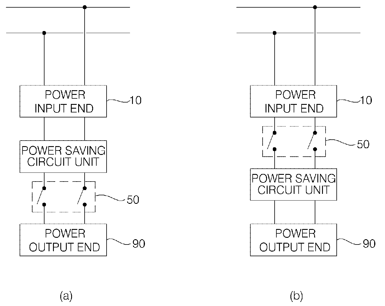
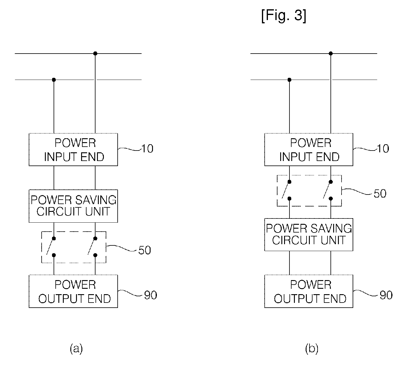
[0046]As illustrated in FIG. 3A, in the electric socket according to the present invention, the power saving circuit unit and the switch unit 50 of the power saving circuit unit are connected to a power input end 10 to which the power is supplied to supply the power to or to interrupt the power from the electronic apparatus or another electric socket connected to a power output end 90. At this time, the switch unit 50 is included in the power saving circuit unit to be operated by the power saving circuit so that the power is supplied to or interrupted from in accordance with the load sensing value of the connected electronic apparatus or another electric socket.

second embodiment

[0047]As illustrated in FIG. 3B, in the electric socket according to the present invention, the switch unit 50 is connected to the power input end 10 and the power saving circuit unit is connected to the switch unit 50 to supply the power to or to interrupt the power from the electronic apparatus or another electric socket connected to the power output end 90. At this time, when the power is cut interrupted by the switch unit 50, since the power supplied to the power saving circuit unit is interrupted, a battery for supplying operating power for driving the power saving circuit unit may be further provided.

[0048]The first and second embodiments of the above-described electric socket will be described in detail. FIG. 4 is a block diagram illustrating the electric socket according to the first embodiment of the present invention. FIG. 5 illustrates a noise removing unit and a switch unit of the electric socket according to the present invention.

[0049]As illustrated in FIG. 4, the elec...

third embodiment

[0129]FIG. 16 is a block diagram illustrating a wall electric socket according to the present invention.

[0130]As illustrated in FIG. 16, the wall electric socket is embedded in a wall of home or a building to interrupt the standby power of an electronic apparatus connected to the wall electric socket. Moreover, the electric socket may include a signal gateway SGW in which a signal is converted and inputted from the exterior.

[0131]In this case, the electric socket includes a communication unit capable of performing data communication according to at least one communication protocol. The communication unit inputs a socket operating signal, like the signal input unit 70, and supplies a signal received from the signal gateway SGW to the electric socket MC (hereinafter, referred to as an ‘main electric socket’ such that the power is supplied or interrupted.

[0132]The main electric socket is connected to the signal gateway SGW via a wired line or a wireless line such that the signal gatewa...


PUM


Abstract

An electric socket is provided. The socket includes a power saving circuit determining operation status of an electronic apparatus or plural electronic apparatus connected to another electric socket according to a load signal to control to supply or automatically interrupt power. It is possible to control power according to operating status of the connected electronic apparatus and to control power supplied to the electronic apparatus connected to a home network. After time has elapsed when the electronic apparatus is not used, power is automatically interrupted so that undesired power consumption due to standby power can be prevented and costs thereof are significantly saved. The electronic apparatus is prevented from accident load inputted from the exterior so that the lifespan of the electronic apparatus can be elongated and user convenience is remarkably improved.

Description

TECHNICAL FIELD[0001]The present invention relates to a plug socket, and more particularly, to a plug socket for supplying power to a connected electronic apparatus to correspond to sensed load current or for automatically cutting off power to cut off standby power to the electronic apparatus regardless of the kind or number of connected electronic apparatuses.BACKGROUND ART[0002]In general, in the case of electronic apparatuses that are frequently used at home such as a TV, a computer, an electronic range, and an audio system, plugs are always plugged in a plug socket so that the plugs remain plugged in the plug socket when the electronic apparatuses are not used for a long time.[0003]At this time, the electronic apparatuses consume a certain amount of standby power when they are not used so that unnecessary power consumption is generated. In order to prevent the standby current from being consumed, the plugs must be plugged out from the plug socket to prevent power from being supp...

Claims


Application Information

Patent Timeline
Patent Type & Authority Applications(United States)
IPC IPC(8): H01H47/00
CPCH01R13/6658Y04S20/225H01R24/76H01R25/006H01R31/065H01R2103/00H02J3/14H02J9/005H02J2009/007Y02B70/3225Y02B90/226Y04S20/16Y04S20/222Y02B70/3233H01R13/70H02J9/007Y02B70/30Y04S20/20H02J2310/60Y04S20/00Y02B90/20
Inventor YANG, KI CHOOLKIM, SUN YOUNG
Owner YANG KI CHOOL
Why Eureka
Try Eureka