Compound touch panel

a touch panel and compound technology, applied in the field of touch panels, can solve the problems of not being able to achieve the effect of avoiding electromagnetic interference, low finger input sensitivity, and many defects of the capacitive touch panel that need to be improved

Inactive Publication Date: 2008-09-25
YOUNG FAST OPTOELECTRONICS
View PDF7 Cites 93 Cited by
  • Summary
  • Abstract
  • Description
  • Claims
  • Application Information

AI Technical Summary

Benefits of technology

[0015]Moreover, the present invention provides a compound touch panel which comprises a capacitive touch panel unit; a resistive touch panel unit and a signal processing unit; the capacitive touch panel unit is overlapped with the resistive touch panel unit; sensing signals from the capacitive touch panel unit and resistive touch panel unit are transferred to the signal processing unit; the signal processing unit having at least one manual operated signal switch for selecting a signal processing mode based on whether sensing signals are from the capacitive touch panel unit or resistive touch panel unit. When the signal processing mode is selected to receive the sensing signals from the capacitive touch panel unit, the upper conductive film and lower conductive film of the resistive touch panel unit are jumped for grounding of the capacitive touch panel unit so as to avoid electromagnetic interference.

Problems solved by technology

However this kind of capacitive touch panel still has many defects necessary to be improved.
For example, the capacitive touch panel is easily interfered by electromagnetic waves so as to induce noises and thus the input signals will be adjudged incorrectly, even the fault operation is induced.
Besides, the sensitivity of the finger input is low, particular to the input of texture, such as Chinese characters.
Although dedicated pens are designed for improving above mentioned defects, it is still not suitable for being used in a small area touch panel with higher precision.
Furthermore, the use of dedicated pen is also inconvenient in many fields, for example the pen is not carried out or the pen is lost.
However the operation of the resistive touch panel is performed by pressure upon the panel, and thus for a long time, the panel will deform or even is destroyed by the repeatedly operation.
As a result, the lifetime of the resistive touch panel is finite.

Method used


Image

  • Compound touch panel
  • Compound touch panel
  • Compound touch panel

Examples


Embodiment Construction

[0021]In order that those skilled in the art can further understand the present invention, a description will be provided in the following in details. However, these descriptions and the appended drawings are only used to cause those skilled in the art to understand the objects, features, and characteristics of the present invention, but not to be used to confine the scope and spirit of the present invention defined in the appended claims.

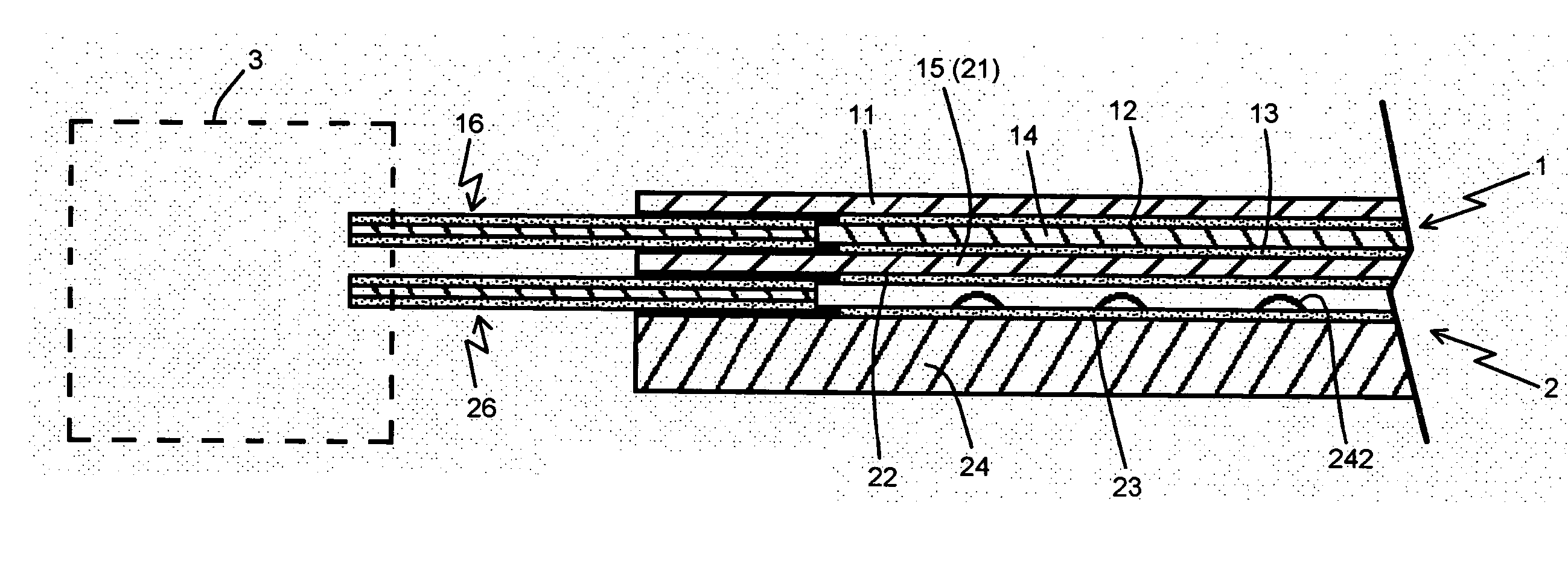
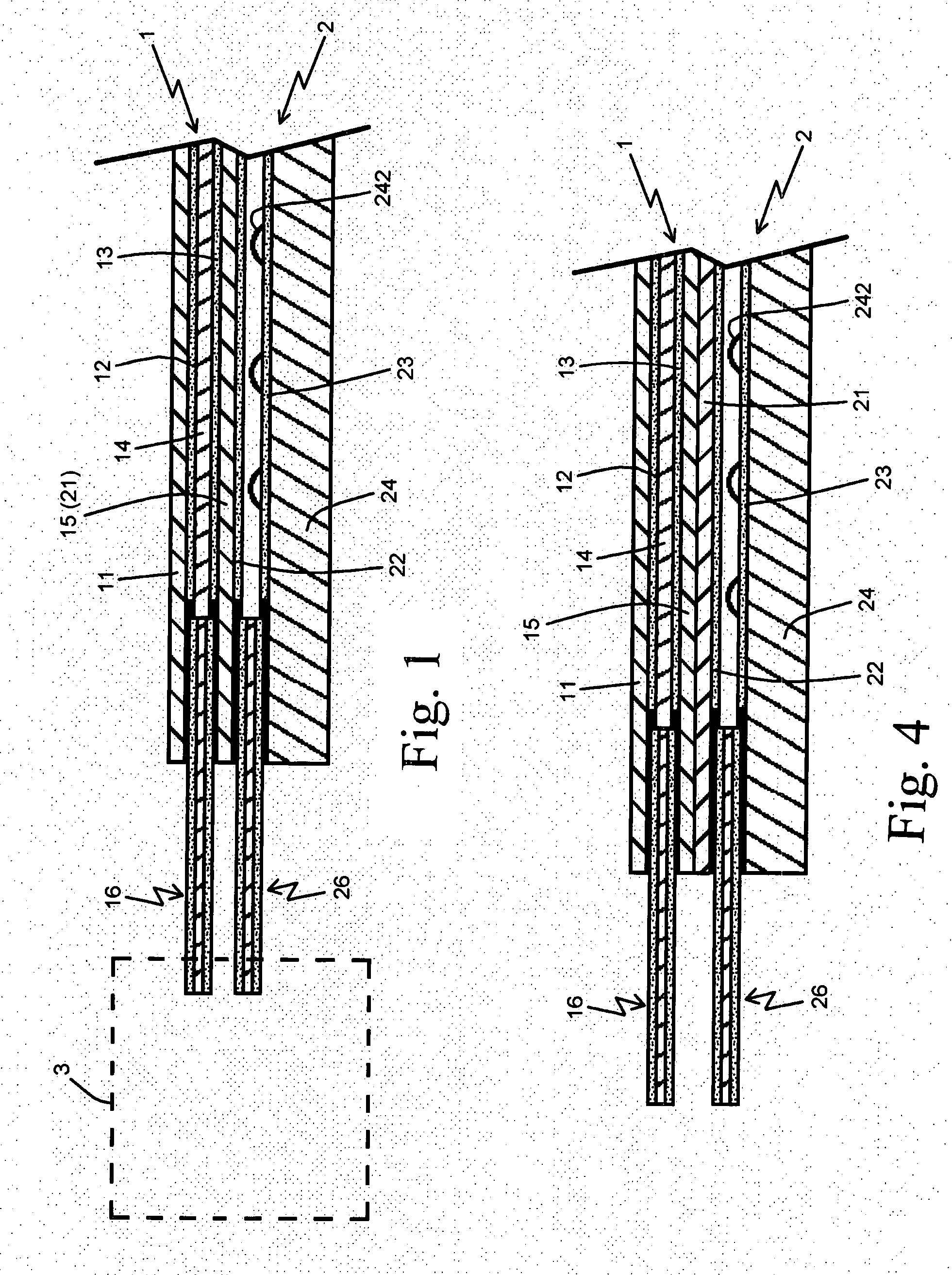
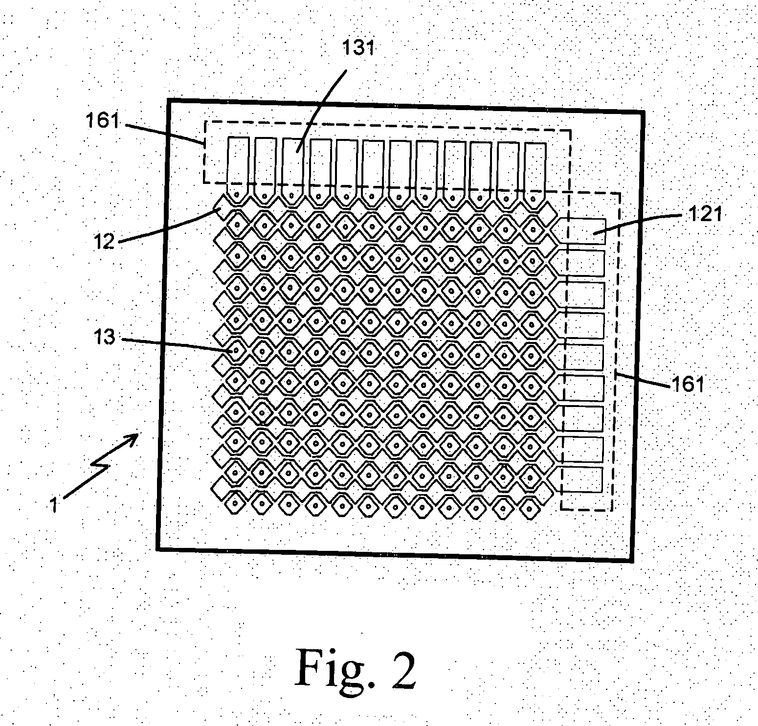
[0022]Referring to FIGS. 1 to 3, the preferred embodiment of the present invention is illustrated. The present invention has the following elements. A capacitive touch panel unit 1 has a panel 11, an X axis sensing layer 12, a Y axis sensing layer 13, an insulation layer 14 installed between the X axis sensing layer 12 and Y axis sensing layer 13, a bottom plate 15 and a first signal output wire bank 16. The panel 11 is a high flexible light transmission insulating film, such as polyester (PET) thin film material. A surface of the panel 11 is coate...


PUM


Abstract

A compound touch panel comprises a capacitive touch panel unit; a resistive touch panel unit and a signal processing unit; the capacitive touch panel unit is overlapped with the resistive touch panel unit; sensing signals from the capacitive touch panel unit and resistive touch panel unit being transferred to the signal processing unit; the signal processing unit having at least one signal determining loop for determining the sensing signals being from the capacitive touch panel unit or the resistive touch panel unit so as to select a predetermined signal processing mode. Or the signal processing unit having a manual operated signal switch for selecting a signal processing mode based on whether sensing signals are from the capacitive touch panel unit or resistive touch panel unit. When the capacitive touch panel unit is selected from receiving signals, the conductive films of the resistive touch panel unit are jumped for grounding.

Description

FIELD OF THE INVENTION[0001]The present invention relates to touch panels, and particularly to a compound touch panel which combines a resistive touch panel unit with a capacitive touch panel unit so that the compound touch panel has the advantages of the two kinds of touch panels, which the defects of the two kinds of touch panels are removed.BACKGROUND OF THE INVENTION[0002]The touch panels are widely used in various electronic devices. In general, the touch panels can be divided into three kinds, one is capacitive touch panels, another is resistive touch panels and the other is electromagnetic touch panels. Every kind of panel has its advantages and thus they are used in different fields, for example the resistive touch panels are used in personal digital assistants (PDAs), electronic dictionaries, handsets, MP3s, digital players, or global positioning systems (GPSs), or other small size electronic devices. The capacitive touch panels are mainly used in the notebooks, or virtual ...

Claims


Application Information

Patent Timeline
Patent Type & Authority Applications(United States)
IPC IPC(8): G06F3/041
CPCG06F3/0416G06F2203/04106G06F3/045G06F3/044G06F3/0445
Inventor YANG, KAI-TI
Owner YOUNG FAST OPTOELECTRONICS
Why Eureka
Try Eureka