Dome Type Camera

a dome-type camera and camera body technology, applied in the field of dome-type cameras, can solve the problems of not being easy to respond to the need and not being able to obtain good images

Inactive Publication Date: 2008-09-25
PANASONIC I PRO SENSING SOLUTIONS CO LTD
View PDF9 Cites 71 Cited by
  • Summary
  • Abstract
  • Description
  • Claims
  • Application Information

AI Technical Summary

Benefits of technology

[0006]A purpose of the invention made in the above-mentioned background is to provide a dome type camera capable of obtaining good shot images in the direction of a depression angle.

Problems solved by technology

However, the conventional dome type camera produces vignetting and cannot obtain good images when shooting in the direction of a depression angle.
Consequently, for example, it has not been easy to respond to the need to shoot around the place where the camera is mounted and to obtain good images therefrom.

Method used


Image

  • Dome Type Camera
  • Dome Type Camera
  • Dome Type Camera

Examples


first embodiment

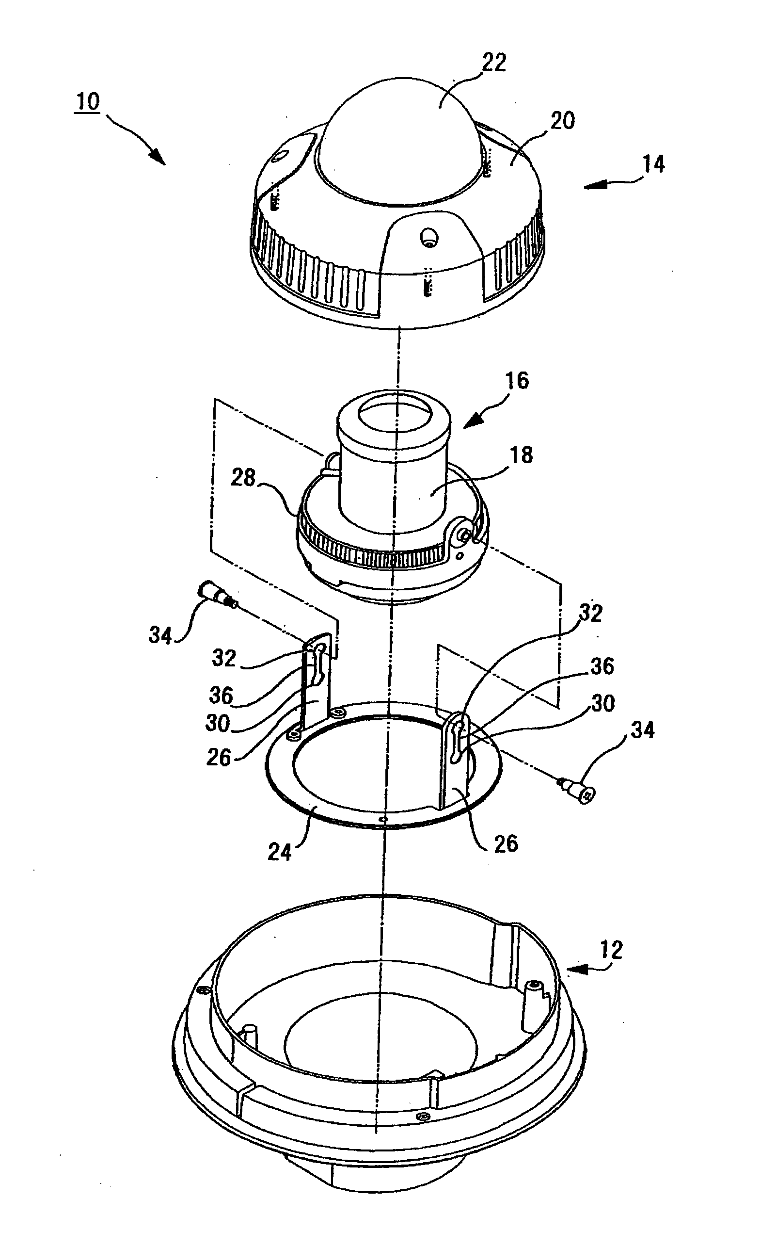
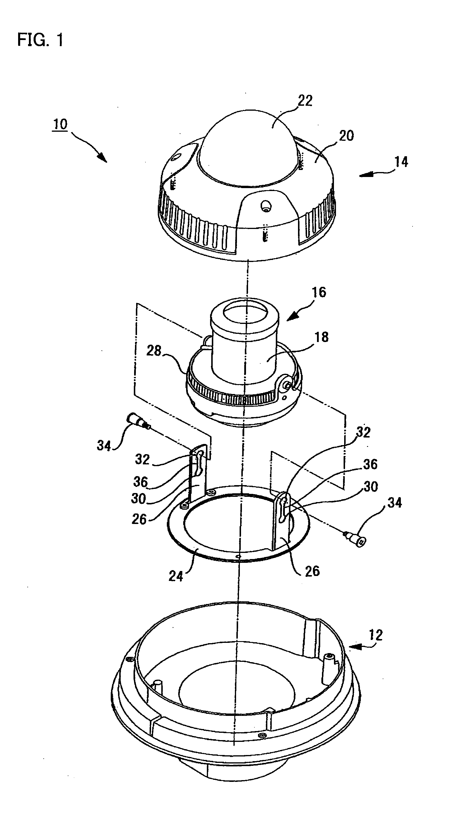
[0047]FIG. 1 shows a dome type camera of the invention. In the embodiment, the dome type camera 10 is a surveillance camera. In the embodiment, in a state where the zenith of the dome faces upward as shown in FIG. 1, the upward direction is referred to as the zenith direction and the lateral direction is referred to as the horizontal direction. The direction of the camera lens is expressed with reference to the horizontal direction, and an angle upward from the horizontal direction is referred to as an elevation angle, while an angle downward from the horizontal direction is referred to as a depression angle. The lens angle of the horizontal direction is 0, and the lens angle of the zenith direction is 90 degrees.

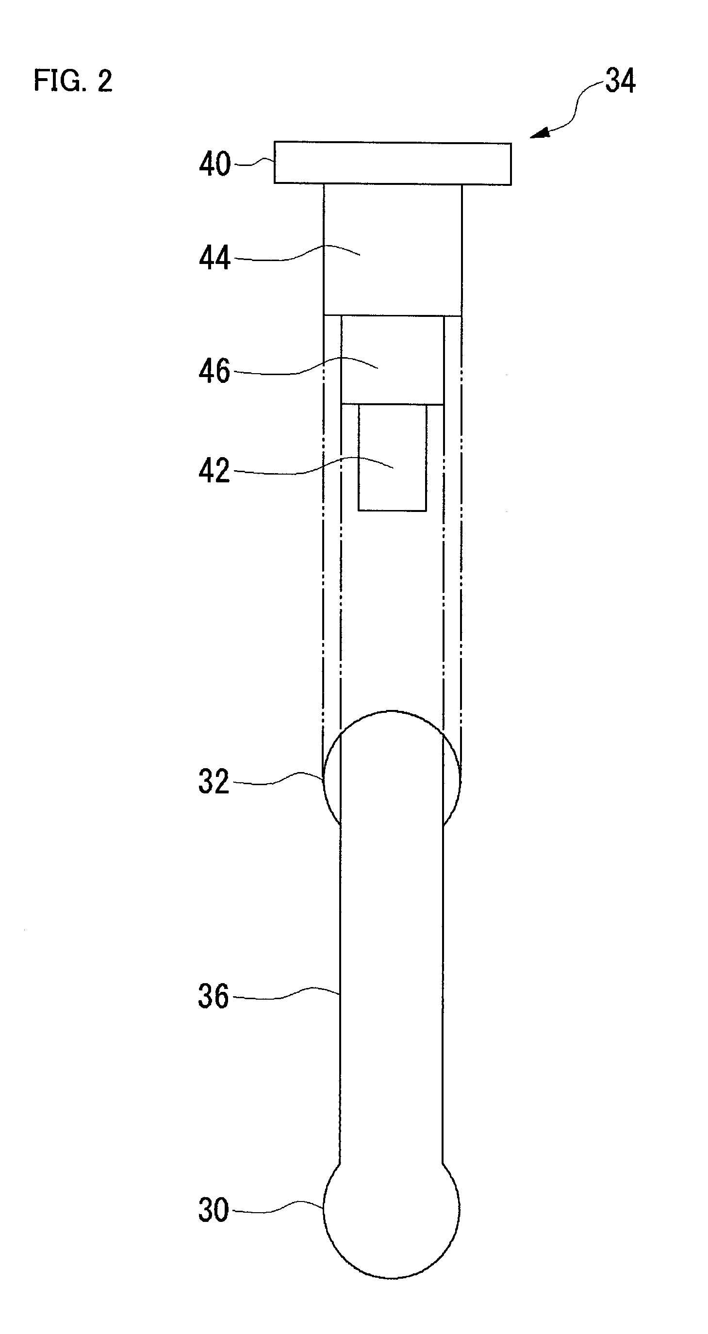
[0048]In FIG. 1, the dome type camera 10 comprises a base 12 and a cover 14 which form a housing. The base 12 is generally circular, and has a mounting structure for a ceiling or other installation locations. The base 12 also rotatably supports a lens 16. The lens 16 is hel...

second embodiment

[0071]Now, a dome type camera of the invention will be described.

[0072]FIG. 4 shows a lens support mechanism of the dome type camera of the embodiment. FIG. 5 is a partial magnified view of FIG. 4. As described below, the dome type camera 50 of the embodiment comprises a cam mechanism as a lens moving mechanism for moving the lens 16 up and down according to the rotation of the lens 16 in the tilt direction. The configuration not shown in the figure such as a base, a cover, and others may be the same as that of the above-described first embodiment, and the description thereof is omitted.

[0073]In FIGS. 4 and 5, a pan section 52 is a ring-shaped thin sheet as is the case with the first embodiment. The pan section 52 is provided with two support walls 54 to stand thereon. The support wall 54 is provided with a slot 56. The lens 16 is rotatably mounted to the slot 56 with a screw 58 so that the lens can be moved up and down in the slot 56.

[0074]Though not shown in the figure, the screw ...


PUM


Abstract

A lens (16) is rotatably provided inside a dome cover (22). The lens (16) is supported so that the center of rotation can be moved from the center of a dome to a position apart therefrom in the zenith direction. A lens moving mechanism for moving the lens (16) according to a rotation in the tilt direction of the lens (16) may be provided. The lens moving mechanism may be a cam structure. The cam structure is set so that the rotation axis of the lens (16) is held at the center of the dome in a predetermined center hold angle range corresponding to the direction of an elevation angle, and that the rotation axis of the lens (16) is moved from the center of the dome in the zenith direction at angles lower than the center hold angle range. Good images can be obtained even when shooting in the direction of a depression angle.

Description

TECHNICAL FIELD[0001]The present invention relates to a dome type camera comprising a lens rotatable in a tilt direction.BACKGROUND ART[0002]A conventional dome type camera comprises a hemispheric dome cover, and a lens provided inside the dome cover rotatably in tilt and pan directions. They are placed so that the center of rotation of the lens is on the optical axis and corresponds to the center of the dome cover, and this placement provides good images. Such a dome type camera is disclosed, for example, in Japanese published patent application No. 2000-155366 (abstract and FIG. 4).[0003]However, the conventional dome type camera produces vignetting and cannot obtain good images when shooting in the direction of a depression angle.[0004]By the way, the direction of a depression angle is a downward direction with reference to the horizontal direction, provided that the zenith direction of the dome is the upward direction. Accordingly, for example, if a dome type surveillance camera...

Claims


Application Information

Patent Timeline
Patent Type & Authority Applications(United States)
IPC IPC(8): H04N7/18G03B15/00G03B5/06G03B17/56H04N5/222H04N5/225
CPCH04N5/2251G03B37/02H04N23/55
Inventor KONISHI, TAKAYUKITATEWAKI, TOSHIKAZU
Owner PANASONIC I PRO SENSING SOLUTIONS CO LTD
Why Eureka
Try Eureka