Image stabilizing actuator and camera furnished therewith

a technology of image stabilizing actuator and camera, which is applied in the direction of optics, instruments, optics, etc., can solve the problems of prone to damage to the receiving surface, and affecting the control of the moving frame, so as to reduce the contact pressure

Inactive Publication Date: 2008-09-25
TAMRON
View PDF3 Cites 49 Cited by
  • Summary
  • Abstract
  • Description
  • Claims
  • Application Information

AI Technical Summary

Benefits of technology

[0085]Next, when the moving frame 14 is moved in what is shown in FIG. 15(a) as the lateral direction along the protected position motion axis A, the steel ball 18 rolls toward the spherical body support surface portions 328a and 330a. When the moving frame 14 is moved to the protected position, the spherical body support surface portion 328a and the spherical body support surface portion 330a are placed in adjacent positions as shown in FIGS. 15(b) and 16. In this state, as shown in FIG. 15(b) and FIG. 17, the steel ball 18 makes surface contact with the spherical body support surface portions 328a and 330a. The spherical body support surface portions 328a and 330b are here formed in a spherical shape with approximately the same diameter as the steel ball 18, therefore the contact surface areas between the steel ball 18 and the spherical body support surface portions 328a and 330a are respectively approximately ¼ of the surface area of the steel ball 18. Hence the steel ball 18 is supported by an area approximately one half its surface area. The steel ball 18, which had been making point contact with the fixed portion spherical body receiving surface 328b and movable portion spherical body receiving surface 330b, thus contacts the spherical body support surface portions 328a and 330a over a very broad surface area, enabling a reduction in the contact pressure sandwiching the steel ball 18.
[0086]In the camera of the third embodiment of the present invention, the steel ball contacts the spherical body support surface portion over a broad area, therefore the contact pressure retaining the steel ball can be reduced, and the steel ball can be held in place.

Problems solved by technology

However, with the type of actuator set forth in JPH10-319465, the problem arises that receiving surfaces are prone to damage due to the extremely small contacting surface area between the steel balls (spherical bodies) and the steel ball receiving surfaces.
This shock force causes a large pressure to be generated, particularly between the small contact surface area steel balls and the receiving surfaces thereof, so that in some cases the receiving surfaces plastically deform under this pressure, and strike marks are left on the steel balls.
Strike marks formed on the receiving surfaces increase the rolling resistance of the steel balls with respect to the receiving surface and adversely affect control of the moving frame due to the sudden change in the rolling resistance around the strike marks.
Moreover, because the receiving surface deforms, the parallelness of the compensating lens attached to the moving frame degrades, leading to the problem of reduced quality of the focused image.

Method used


Image

  • Image stabilizing actuator and camera furnished therewith
  • Image stabilizing actuator and camera furnished therewith
  • Image stabilizing actuator and camera furnished therewith

Examples


first embodiment

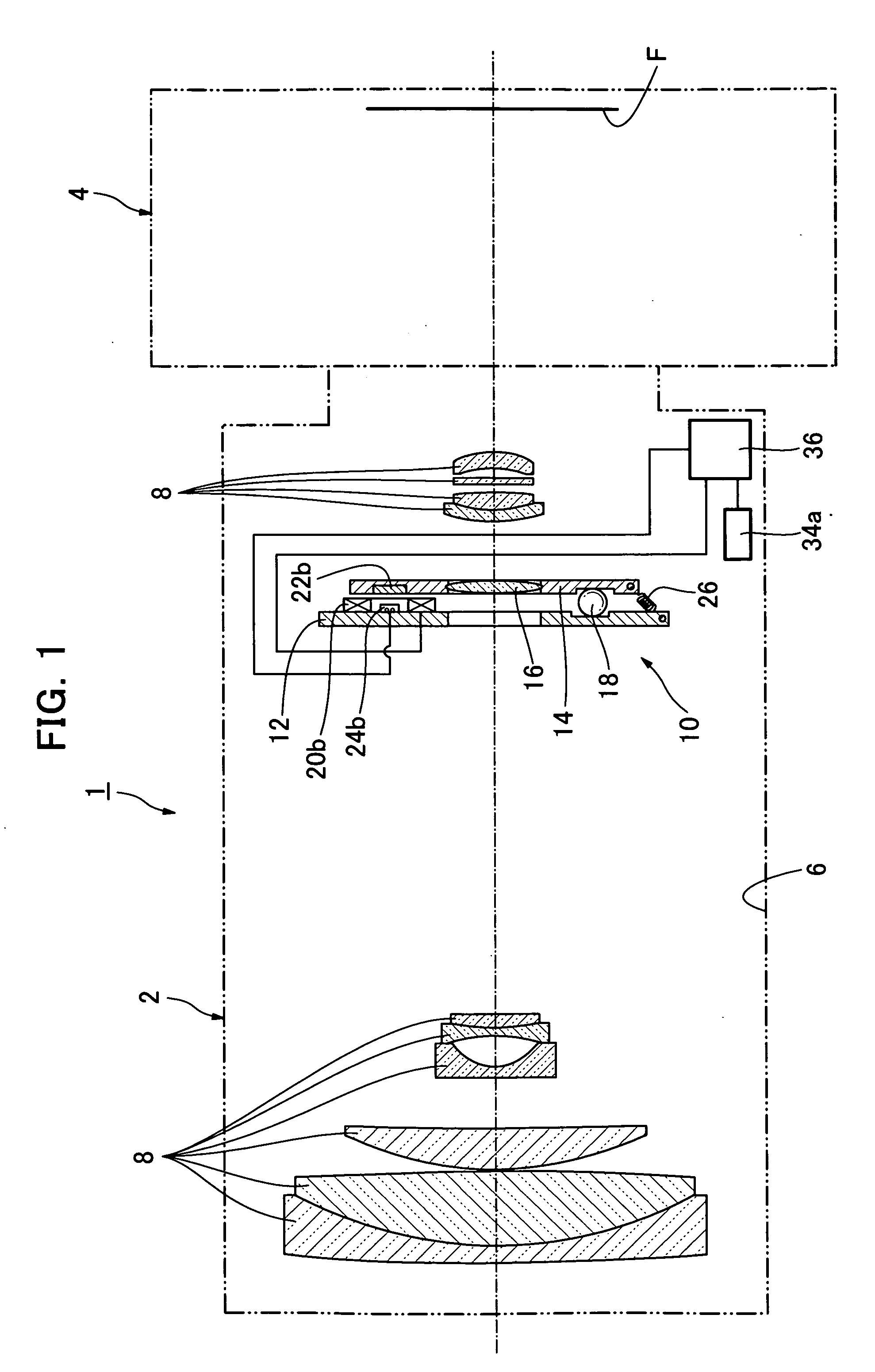
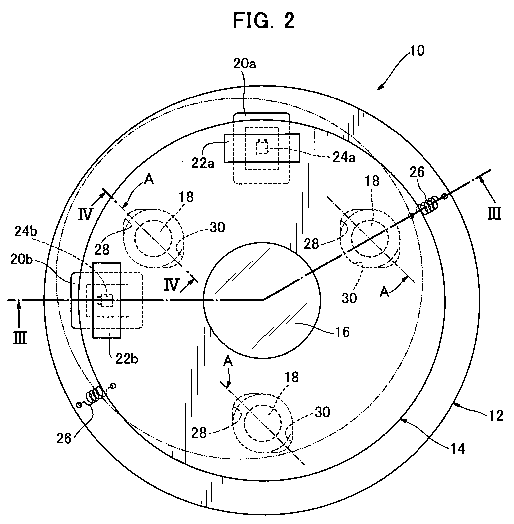
[0023]We next discuss preferred embodiments of the present invention with reference to the attached figures. First we discuss the present invention with reference to FIGS. 1 through 7. FIG. 1 is a cross sectional view of the camera of this embodiment.

[0024]As shown in FIG. 1, a camera 1 of the first embodiment has a lens unit 2 and a camera main body 4. The lens unit 2 has a lens barrel 6, a plurality of imaging lenses 8 arrayed within the lens barrel, an actuator 10 for moving a image blur compensation lens 16 among the imaging lenses 8 within a predetermined plane, and gyros 34a and 34b (only34a is shown in FIG. 1) serving as a vibration detection means for detecting vibration in the lens barrel 6.

[0025]The lens unit 2 is attached to the camera main body 4 and constituted so that entering light is imaged on a film surface F.

[0026]The approximately cylindrical lens barrel 6 holds within it a plurality of the imaging lenses 8, and focusing is performed by moving a portion of the ima...

second embodiment

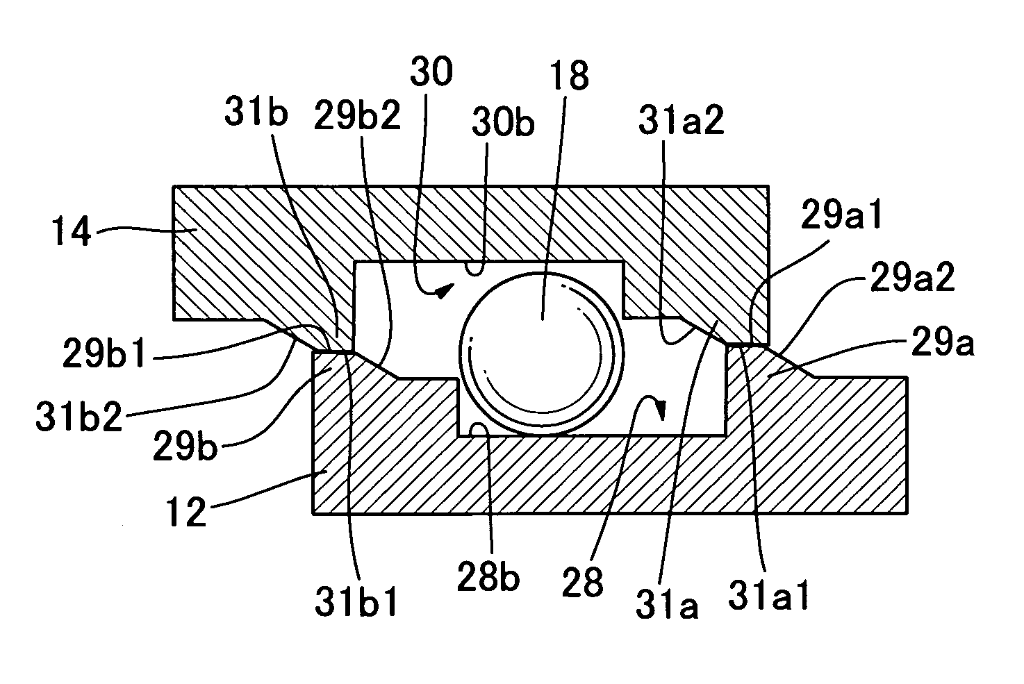
[0078]In the second embodiment camera of the present invention, the fixed frame plane portion and the moving frame plane portion make direct contact in the protected position, therefore the actuator can be compactly constituted without the thickness of the actuator becoming too thick in the protected position.

[0079]Also, in the camera of the present embodiment, the steel ball is placed in a freely movable state in the protected position, and the position at which the steel ball makes contact with the fixed portion spherical body receiving surface and the movable portion spherical body receiving surface changes randomly. This permits the prevention of eccentric wear by which only certain locations on the steel balls are worn.

[0080]Next, referring to FIGS. 13 through 17, we discuss a camera according to a third embodiment of the invention. The camera of this embodiment differs from the above-described first and second embodiments in the constitution of its built-in actuator fixed fram...

third embodiment

[0086]In the camera of the present invention, the steel ball contacts the spherical body support surface portion over a broad area, therefore the contact pressure retaining the steel ball can be reduced, and the steel ball can be held in place.

[0087]We have discussed preferred embodiments of the present invention, but various changes could also be applied to the above-described embodiments. In particular, in the embodiments discussed above the present invention was applied to a film camera, but the present invention could also be freely applied to any desired camera used for still or moving picture imaging, such as digital cameras, video cameras, and the like.

[0088]In the embodiments discussed above, the protected position was set up in a position to which the moving frame was translated from the image stabilization control operational center position, but the protected position can also be set up at a position to which the moving frame is rotated from the operational center positio...


PUM


Abstract

Problem: To provide an actuator capable of preventing damage to spherical bodies and their receiving surfaces when subjected to a shock force.
Solution Means: The present invention is an actuator (10) for stabilizing images by moving an imaging lens, comprising a fixed portion (12), a movable portion (14) to which an imaging lens is attached, a plurality of spherical bodies (18) for supporting the movable portion, a fixed portion spherical body receiving surface (28b) disposed on the fixed portion and contacting the spherical bodies, a movable portion spherical body receiving surface (30b) disposed on the movable portion and contacting the spherical bodies, a biasing means (26) for sandwiching the spherical bodies between the fixed portion spherical body receiving surface and the movable portion spherical body receiving surface, and spherical body receiving surface protection means (29, 30) which, when image stabilization control is not in effect, reduce the contact pressure acting on the spherical bodies so as to sandwich the spherical bodies when the movable portion is moved to a predetermined protected position.

Description

TECHNICAL FIELD[0001]The present invention relates to an actuator and a camera provided therewith, and in particular to an actuator for moving an imaging lens within a plane perpendicular to its optical axis to prevent image blurring, and a camera furnished therewith.BACKGROUND ART[0002]A lens shifting device (actuator) is set forth in JP H.10-319465 (Patent Document 1). In this lens shifting device, a moving frame attached to a compensating lens is supported by three steel balls so as to be able to move in parallel, and is driven by a linear motor to prevent image blurring. In this type of lens shifting device, virtually no rubbing resistance arises when the moving frame moves, therefore the moving frame can be driven with a small drive force.Patent Document 1[0003]JP H.10-319465DISCLOSURE OF THE INVENTIONProblems to Be Solved by the Invention[0004]However, with the type of actuator set forth in JPH10-319465, the problem arises that receiving surfaces are prone to damage due to the...

Claims


Application Information

Patent Timeline
Patent Type & Authority Applications(United States)
IPC IPC(8): G02B27/64
CPCG02B27/646
Inventor OTSUKA, HIROSHI
Owner TAMRON
Why Eureka
Try Eureka