This helps you quickly interpret patents by identifying the three key elements:
Problems solved by technology
Method used
Benefits of technology
Benefits of technology
[0036]The exemplary techniques discussed herein that are used to determine the length of the impulse event can also be extended to determining the repetition period of the impulse noise event, i.e., how often is impulse noise occurring. The repetition period can be important, because the period has an effect on the FIP setting that is used. For example, if the interleaving spreads an impulse noise event over a period of time that exceeds the impulse period, then
Problems solved by technology
Communications systems often operate in environments that produce impulse noise.
For example, DSL systems operate on telephone lines and experience impulse noise from many external sources including telephones, AM radio, HAM radio, other DSL services on the same line or in the same bundle, other equipment in the home, etc.
Impulse noise protection is handled with interleaving and FEC, but the current xDSL procedure at least does not provide specific states to enable training for the selection of the appropriate interleaving and FEC parameters.
An exemplary problem associated with traditional communication systems is that they use traditional Signal to Noise Ratio (SNR) measurement techniques to determine the SNR of the channel.
These traditional methods for measuring SNR do not correctly measure the impact of impulse noise and do not have the noise capability to determine how the system should be configured to handle impulse noise.
One exemplary problem with this approach is that it is time consuming and can result in sub-optimum user rates.
If a value of 4 is used as a second INP value, it still will not provide adequate impulse noise protection and bit errors will occur.
Clearly, the connection needs to be re-initialized every time there is a new INP configuration chosen and this trial and error technique proves to be very time consuming.
As a result, user data throughput is greatly degraded since the additional FEC redundancy will be three times higher than what is actually needed.
In additional to the above drawbacks, the related systems do not have the ability to actually measure the length or repetition period of impulse noise which can both be used to determine an appropriate impulse noise protection setting.
However, since the operator is not capable of making the receivertrade offs stated above, such as the data rate, latency, and the like, the process will often lead to a sub-optimum result.
This is true since when the FEC / interleaving is enabled, the impulse noise event will be spread over a large time period and it will be more difficult to determine the length of the original impulse.
Method used
Image
Click on the blue label to locate the original text in one second.
Reading with bidirectional positioning of images and text.
[0079]This section describes an example of FIP settings for On-Line INP adaptation for DSL. In this example only the number of information bytes in a codeword (K) and the number of parity bytes in a codeword (R) are updated on-line. The Codeword Size (N) and Interleaver Depth (D) are not changed. This means that the latency (and interleaver memory size) and the line rate are not modified on-line. Since N=K+R this places restrictions on the allowed values for K and R.
1st Setting—{Approximate User Data Rate=3.968 Mbps, Line Rate=4.096 Mbps, N=128, K=124, R=4, S=1, D=64, Latency=16 msec, INP=1}
2nd Setting—{Approximate User Data Rate=3.840 Mbps, Line Rate=4.096 Mbps, N=128, K=120, R=8, S=1, D=64, Latency=16 msec, INP=2}
3nd Setting—{Approximate User Data Rate=3.584 Mbps, Line Rate=4.096 Mbps, N=128, K=112, R=16, S=1, D=64, Latency=16 msec, INP=4}
[0080]The On-line INP adaptation process is restricted to only modify the number of information bytes in a cod...
[0081]This section describes an example of FIP settings for On-Line INP adaptation for DSL. In this example only the Codeword Size (N) and the number of parity bytes in a codeword (R) are updated on line. The number of information bytes in a codeword (K) and Interleaver Depth (D) are not changed and therefore the user data rate does not change. This means that the latency (and interleaver memory size) and the line rate are modified on-line. Since N=K+R this places restrictions on the allowed values for K and R.
1st Setting—{Approximate User Data Rate=3.968 Mbps, Line Rate=4.096 Mbps, N=128, K=124, R=4, S=1, D=64, Latency=16 msec, INP=1}
2nd Setting—{Approximate User Data Rate=3.968 Mbps, Line Rate=4.224 Mbps, N=132, K=124, R=8, S=1, D=64, Latency=16 msec, INP=2}
3nd Setting—{Approximate User Data Rate=3.968 Mbps, Line Rate=4.480 N=128, K=124, R=16, S=1, D=64, Latency=16 msec, INP=4}
[0082]In this example the Line Rate is modified on-line. For this reaso...
PUM
Abstract
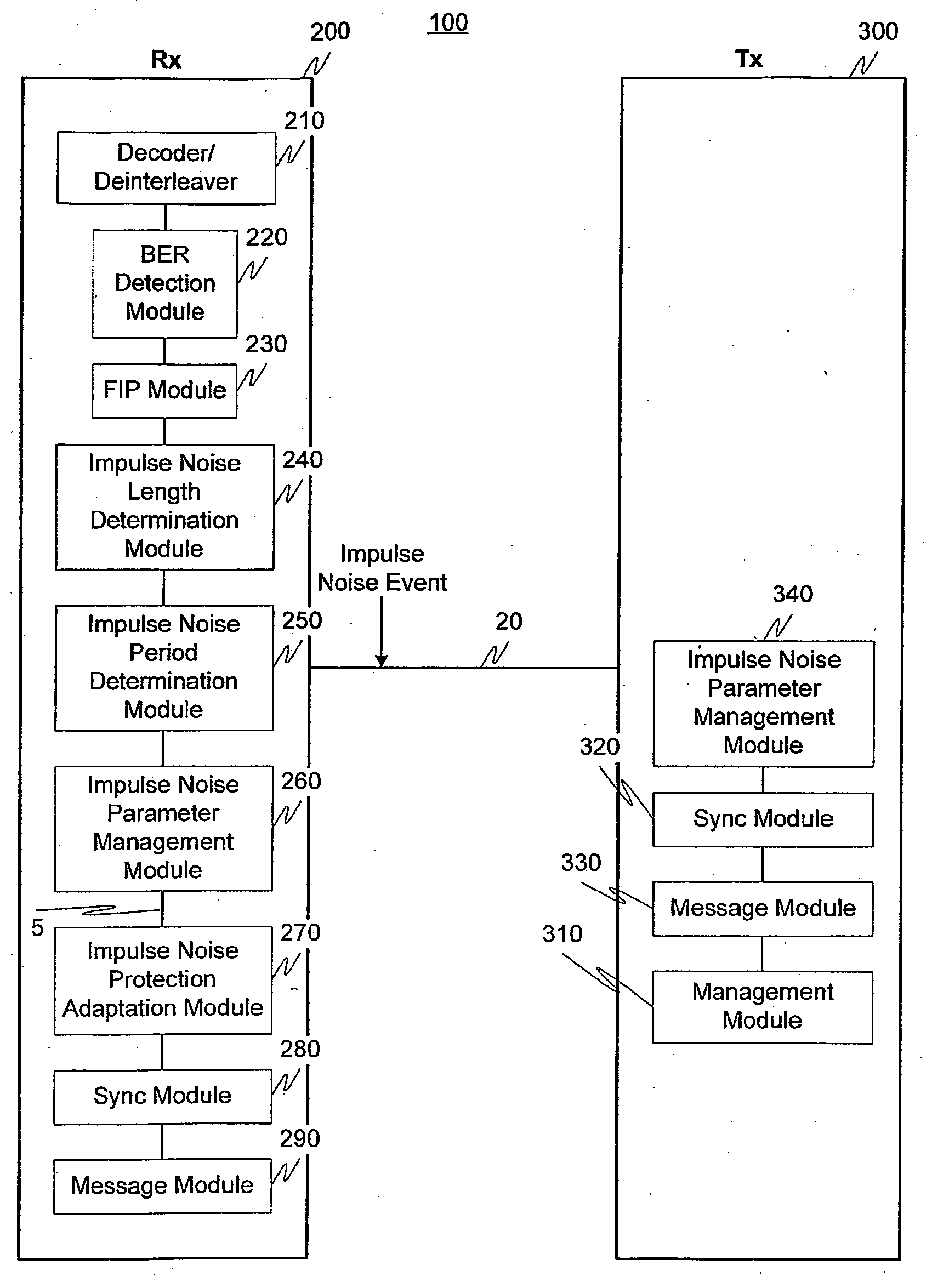
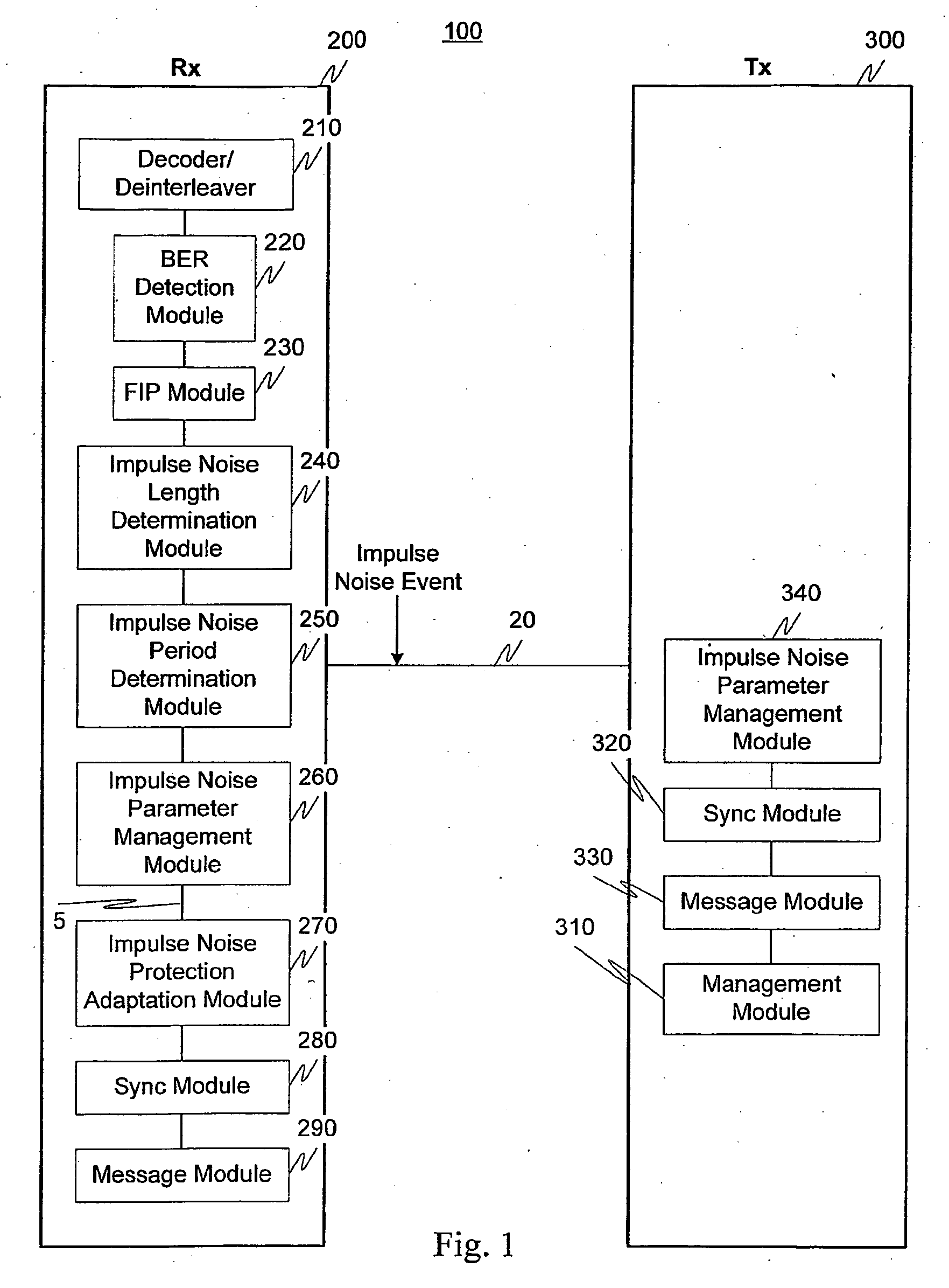
Evaluation of the impact of impulse noise on a communication system can be utilized to determine how the system should be configured to adapt to impulse noise events. Moreover, the system allows for information regarding impulse noise events, such as length of the event, repetition period of the event and timing of the event, to be collected and forwarded to a destination. The adaptation can be performed during one or more of Showtime and initialization, and can be initiated and determined at either one or more of a transmitter and a receiver.
Description
RELATED APPLICATION DATA[0001]This application claims the benefit of and priority under 35 U.S.C. §119(e) to U.S. Provisional Application No. 60 / 549,804, entitled “On-Line Impulse Noise Protection (INP) Adaptation,” filed Mar. 3, 2004, and U.S. Provisional Application No. 60 / 555,982, entitled “Impulse Noise Protection (INP) Training,” filed Mar. 24, 2004, both of which are incorporated herein by reference in their entirety.BACKGROUND[0002]1. Field of the Invention[0003]This invention generally relates to communication systems. In particular, an exemplary aspect of this invention relates to impulse noise protection adaptation. Another exemplary aspect of this invention relates to impulse noise length and period determination and use thereof for impulse noise protection adaptation.[0004]2. Description of Related Art[0005]Communications systems often operate in environments that produce impulse noise. Impulse noise is a short-term burst of noise that is higher than the normal noise tha...
Claims
Application Information
Patent Timeline
Application Date:The date an application was filed.
Publication Date:The date a patent or application was officially published.
First Publication Date:The earliest publication date of a patent with the same application number.
Issue Date:Publication date of the patent grant document.
PCT Entry Date:The Entry date of PCT National Phase.
Estimated Expiry Date:The statutory expiry date of a patent right according to the Patent Law, and it is the longest term of protection that the patent right can achieve without the termination of the patent right due to other reasons(Term extension factor has been taken into account ).
Invalid Date:Actual expiry date is based on effective date or publication date of legal transaction data of invalid patent.

