
Event detection in visual surveillance systems

a video surveillance and event detection technology, applied in the direction of direction finders, instruments, computing, etc., can solve the problem of difficulty in ensuring the attention of a person when observing video, and achieve the effect of greater flexibility and thus discriminative power

Inactive Publication Date: 2008-09-25
IBM CORP
View PDF15 Cites 41 Cited by
  • Summary
  • Abstract
  • Description
  • Claims
  • Application Information

AI Technical Summary

Benefits of technology

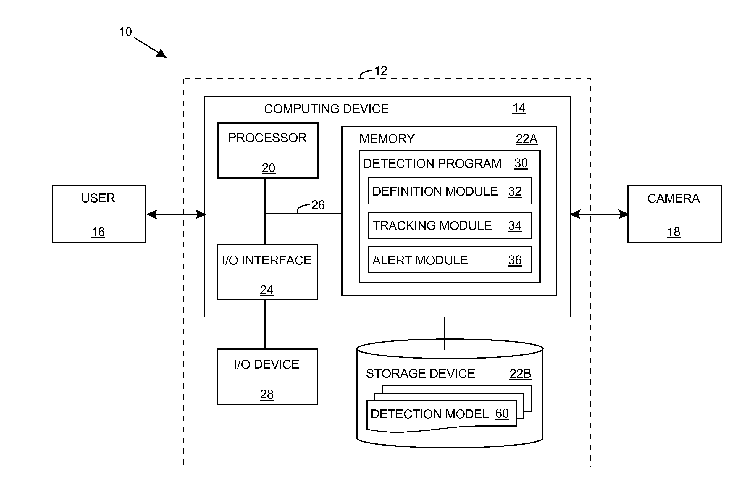
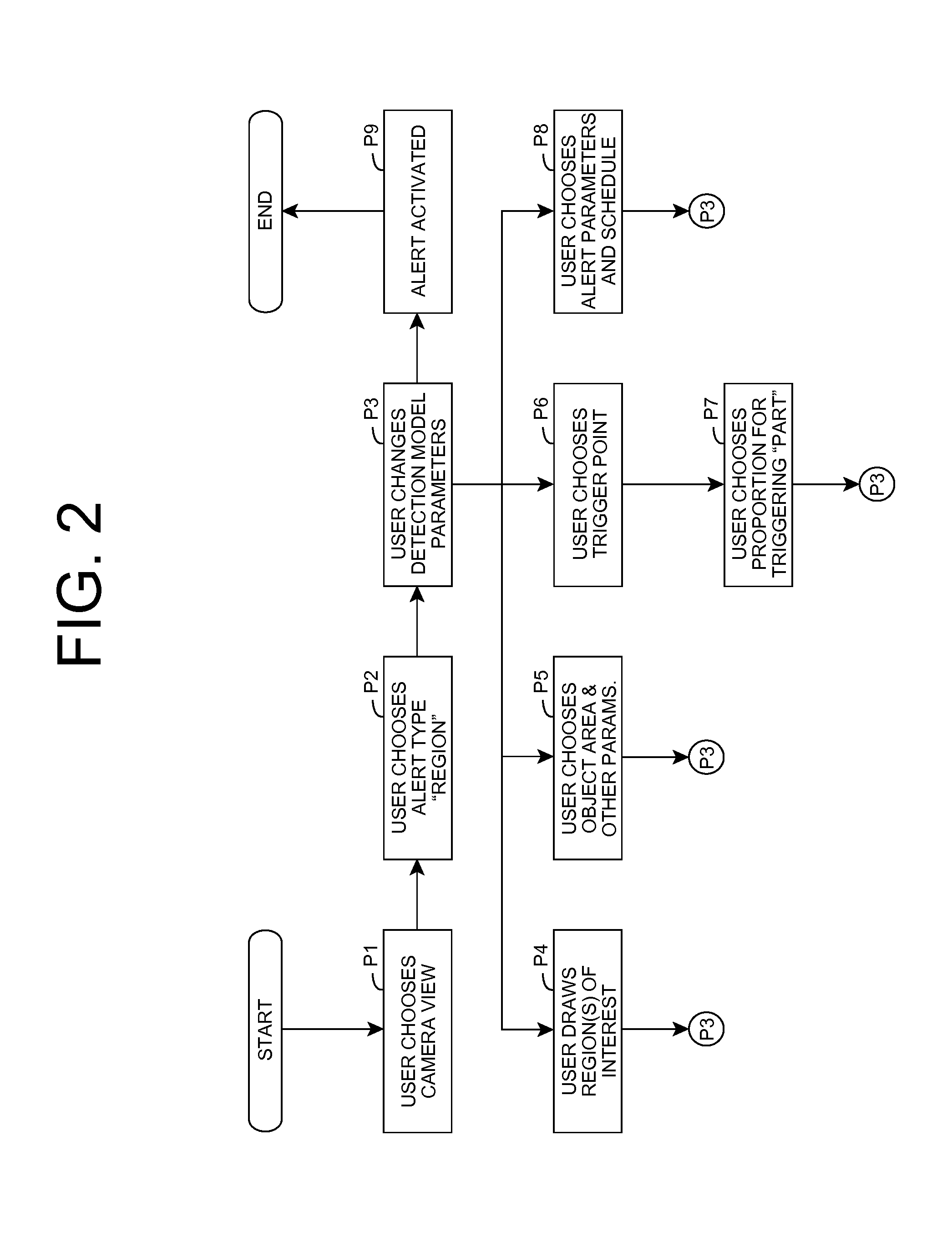
[0006]Aspects of the present invention are directed to a solution for detecting events in video, for example, video from a surveillance camera. The solution allows a user to pre-specify events that the user is interested in and will notify the user when those events occur. Such systems exist, and detect events, called “alerts” or “alarms” of types including the following: motion detection, movement across tripwire, movement in a specified direction, etc. Aspects of the solution provide an alternative method of defining and detecting a video event, with greater flexibility and thus discriminative power. In particular, a region of interest within a series of video images of the video is monitored. An object at least partially visible within the series of video images is tracked and a fiducial region of the object is identified. The fiducial region is one or more points and / or area(s) of the object, which are relevant in determining whether an alert should be generated. The fiducial region is monitored with respect to the region of interest and a restricted behavior. When the restricted behavior is detected with respect to the region of interest, an alert is generated.

Problems solved by technology

Because of this, it is very difficult for a person to maintain attention when observing video.
More complex systems may allow the user to define criteria for the duration or area of the motion, or even its direction.

Method used


Image

  • Event detection in visual surveillance systems
  • Event detection in visual surveillance systems
  • Event detection in visual surveillance systems

Examples


Embodiment Construction

[0017]This disclosure discusses a solution for detecting alerts / events in an automatic visual surveillance system. An example of this type of surveillance system is known as the “Smart Surveillance System” and is described in A. Hampapur, L. Brown, J. Connell, S. Pankanti, A. W. Senior, and Y.-L. Tian, Smart Surveillance: Applications, Technologies and Implications, IEEE Pacific-Rim Conference on Multimedia, Singapore, December 2003, which is incorporated herein by reference.

[0018]As indicated above, aspects of the invention provide a solution in which a region of interest within a series of video images is monitored. An object at least partially visible within the series of video images is tracked and a fiducial region of the object is identified. The fiducial region is one or more points and / or area(s) of the object, which are relevant in determining whether an alert should be generated. The fiducial region is monitored with respect to the region of interest and a restricted behav...


PUM


Abstract

An improved solution for detecting events in video is provided, in which a region of interest within a series of video images of the video is monitored. An object at least partially visible within the series of video images is tracked and a fiducial region of the object is identified. The fiducial region is one or more points and / or area(s) of the object, which are relevant in determining whether an alert should be generated. The fiducial region is monitored with respect to the region of interest and a restricted behavior. When the restricted behavior is detected with respect to the region of interest, an alert is generated.

Description

REFERENCE TO PRIOR APPLICATIONS[0001]The current application claims the benefit of co-pending U.S. Provisional Application No. 60 / 895,867, titled “Alert detection in visual surveillance systems”, which was filed on 20 Mar. 2007, and which is hereby incorporated by reference.TECHNICAL FIELD OF THE INVENTION[0002]Aspects of the present invention relate to the field of video camera systems. More particularly, an embodiment of the present invention relates to the field of automatically detecting events in video.BACKGROUND OF THE INVENTION[0003]In typical surveillance video, the frequency of occurrences of notable events is relatively low. Either there is no change in the scene observed by the camera, or the changes are routine and not of interest. Because of this, it is very difficult for a person to maintain attention when observing video. Automatic video surveillance systems attempt to overcome this problem by using computer processing to analyze the video and determine what activity ...

Claims


Application Information

Patent Timeline
Patent Type & Authority Applications(United States)
IPC IPC(8): G06K9/00
CPCG01S3/7864G06K9/6253G06K9/00771G06V20/52G06F18/40
Inventor SENIOR, ANDREW W.TIAN, YING-II
Owner IBM CORP
Learn More