Dynamic spinal stabilization system and method of using the same

a spinal stabilization and dynamic technology, applied in the field of spinal support devices, can solve the problems of limiting the range of motion of the spine, affecting the function of the spine, and affecting the patient's recovery, so as to achieve the effect of stabilizing the spine and stabilizing the spin

Active Publication Date: 2008-09-25
ZIMMER BIOMET SPINE INC
View PDF38 Cites 194 Cited by
  • Summary
  • Abstract
  • Description
  • Claims
  • Application Information

AI Technical Summary

Benefits of technology

[0018]A method of stabilizing the spine in accordance with an alternate embodiment of the invention includes securing at least first and second anchors to respective first and second vertebrae of the spine, and providing a plethora of connectors for coupling a flexible assembly to the anchors. The flexible assembly includes at least one spacer with first and second opposed end faces. The connector has at least a first outer surface that forms an angle with respect to an axis of the anchor when coupled thereto. The method further includes determining the angle of the first outer surface so that the first outer surface engages substantially all of one of the end faces of the spacer when the flexible assembly is coupled to the spine; constructing the flexible assembly using a connector having a first outer surface with the determined angle; and then coupling the flexible assembly to the anchors to stabilize the spine.

Problems solved by technology

Patients that suffer from such conditions usually experience extreme and debilitating pain, as well as diminished nerve function.
These spinal disorders, pathologies, and injuries limit the spine's range of motion, or threaten the critical elements of the nervous system housed within the spinal column.
For example, it has been shown that spine fusion decreases function by limiting the range of motion for patients in flexion, extension, rotation and lateral bending.
Furthermore, it has been shown that spine fusion creates increased stresses and therefore, accelerated degeneration of adjacent non-fused segments.
Another disadvantage of fusion is that it is an irreversible procedure.
This may be due to the specific vertebral physiology to which the stabilization system is being applied, the geometry of the components or the non-idealized placement of the anchors in the vertebrae.
In any event, the resulting reduction in contact area between the spacer and anchors may diminish the capacity of the stabilization system to efficiently transmit applied loads to the vertebrae to which the anchors are attached.
This may result in a reduction in the support provided by the stabilization system, a loss of the pre-tensioning of the system, or otherwise affect the stabilization system in a manner that impacts treatment of the spine.

Method used


Image

  • Dynamic spinal stabilization system and method of using the same
  • Dynamic spinal stabilization system and method of using the same
  • Dynamic spinal stabilization system and method of using the same

Examples


Embodiment Construction

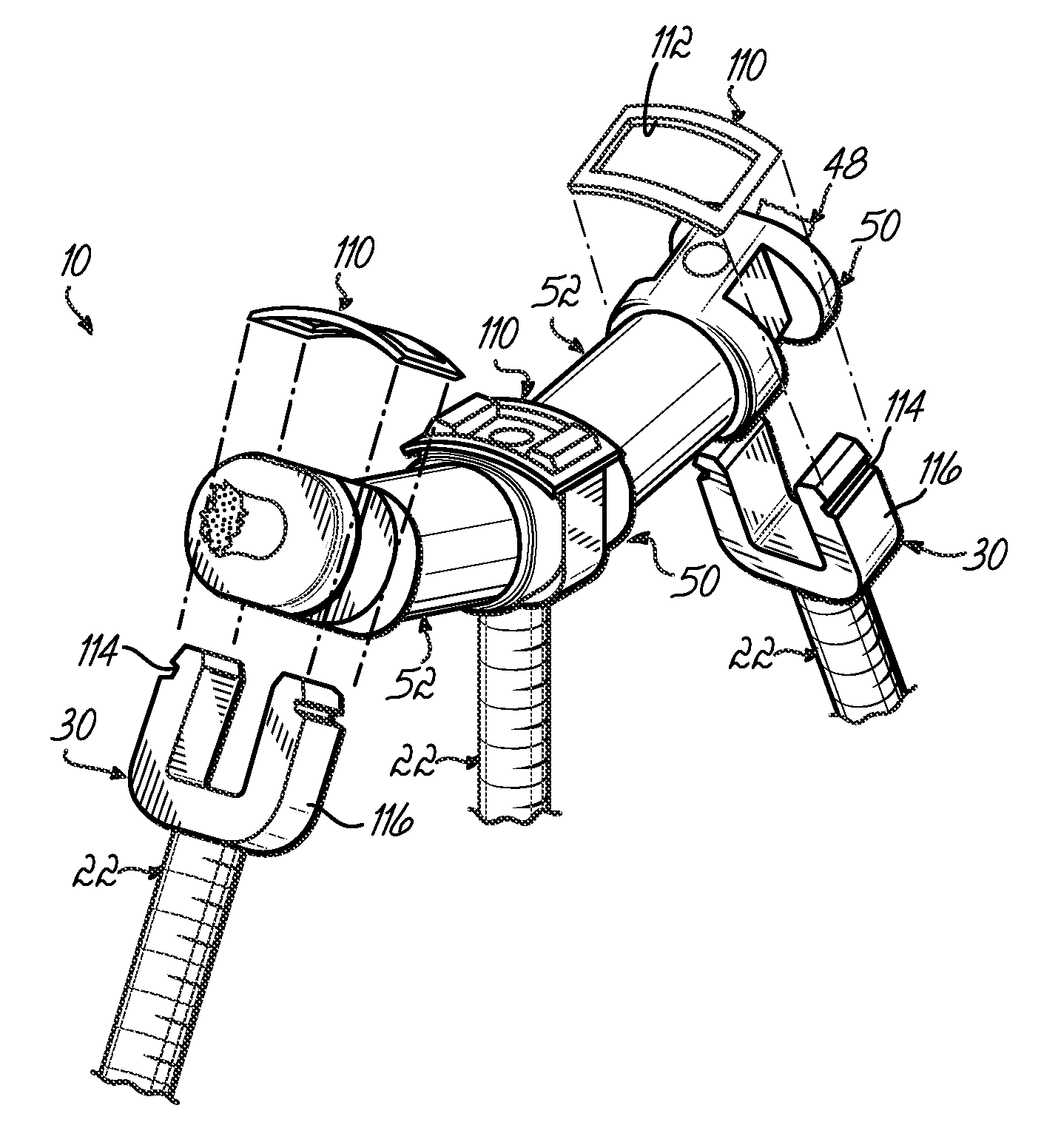
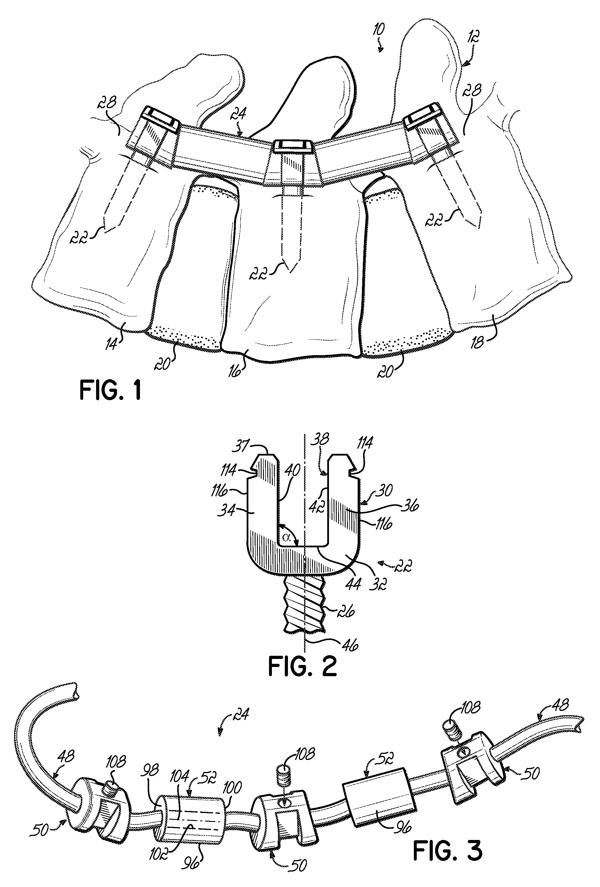
[0029]Referring now to the drawings, and to FIG. 1 in particular, a spinal stabilization system 10 is shown implanted into a segment of a spine 12 defined by serially positioned spinal elements in the form of adjacent vertebrae 14, 16, 18 that are separated by discs 20. The stabilization system 10 includes anchors 22 installed in vertebrae 14, 16, 18 and a flexible assembly 24 coupled to and extending between the anchors 22 to control abnormal motion of the spine 12, while otherwise leaving the spinal segment mobile.

[0030]FIG. 2 illustrates an exemplary embodiment of an anchor used in the spinal stabilization system 10 in more detail. As shown in this figure, each anchor 22 may be configured as a pedicle bone screw having a threaded portion 26 adapted to facilitate coupling between the anchor 22 and the pedicle 28 (FIG. 1) of the vertebrae 14, 16, 18 and a head portion 30 adapted to couple to the flexible assembly 24. While pedicle screws are shown and described herein, those of ord...


PUM


Abstract

A spinal stabilization system includes at least two anchors having a bone attachment portion and a head portion and a flexible assembly coupled to the anchors. The flexible assembly includes a flexible cord, at least two connectors slidably mounted to the flexible cord, and at least one spacer slidably mounted to the cord between adjacent connectors. Each connector couples with a head portion of an anchor. The flexible assembly may be assembled and appropriately adjusted outside the body prior to it being coupled to the anchors. In addition, the connectors may include angled outer surfaces that provide enhanced engagement with the ends of the spacer. A method of stabilizing the spine includes securing anchors to the spine, assembling a flexible assembly outside the body, and coupling the flexible assembly to the anchors. The method may further include providing connectors with angled surfaces to provide enhanced engagement with the spacer.

Description

FIELD OF THE INVENTION [0001]The present invention generally relates to spinal support devices, and more particularly to an apparatus and method for dynamically stabilizing the spine.BACKGROUND OF THE INVENTION [0002]The spinal column is a highly complex system of bones and connective tissues that provides support for the body and protects the delicate spinal cord and nerves. The spinal column includes a series of vertebrae stacked one on top of the other, each vertebral body including a portion of relatively weak cancellous bone and a portion of relatively strong cortical bone. Situated between each vertebral body is an intervertebral disc that cushions and dampens compressive forces experienced by the spinal column. A vertebral canal containing the spinal cord and nerves is located posterior to the vertebral bodies. In spite of the complexities, the spine is a highly flexible structure, capable of a high degree of curvature and twist in nearly every direction. For example, the kin...

Claims


Application Information

Patent Timeline
Patent Type & Authority Applications(United States)
IPC IPC(8): A61B17/70A61B17/08A61B17/04A61B17/58
CPCA61B17/701A61B17/7032A61B17/7031A61B17/7008
Inventor BOSCHERT, PAUL F.
Owner ZIMMER BIOMET SPINE INC
Why Eureka
Try Eureka