Modular pedicle screw system

a pedicle screw and module technology, applied in the field of medical devices, can solve the problem of limiting the potential for cross-threading of the set screw thread in the rod holding element, and achieve the effect of reducing the potential for cross-threading of the set screw thread

Active Publication Date: 2008-09-25
THE CENT FOR ORTHOPEDIC RES & EDUCATION
View PDF48 Cites 50 Cited by
  • Summary
  • Abstract
  • Description
  • Claims
  • Application Information

AI Technical Summary

Benefits of technology

[0008]The system proposed herein allows for a multipurpose pedicle screw assembly having multiple modular inserts. The combination of modular inserts allows the screw assembly to perform with different functionalities that would be applicable with different surgical procedures. The selection of a particular kind of modular insert can determine the assembly functionality. Th

Problems solved by technology

The tabs on the rod adapting element also function as a guide to assist the surgeon in placing the set screw and ensure proper alignment of the

Method used


Image

  • Modular pedicle screw system
  • Modular pedicle screw system
  • Modular pedicle screw system

Examples


first embodiment

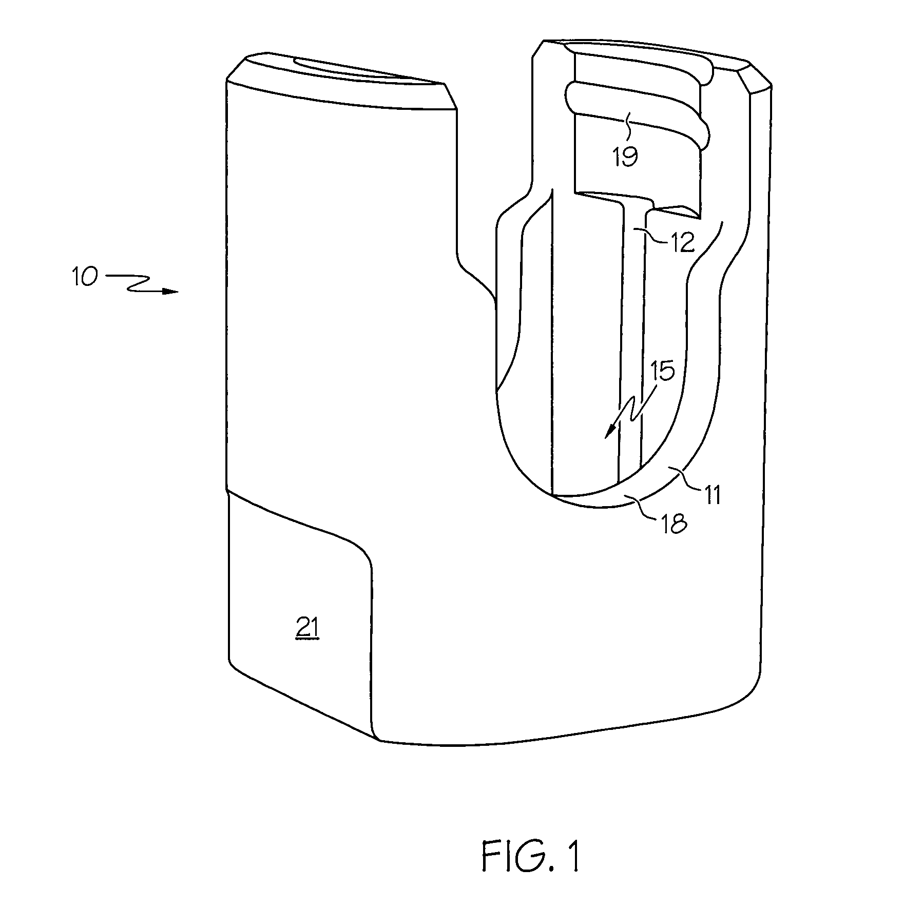
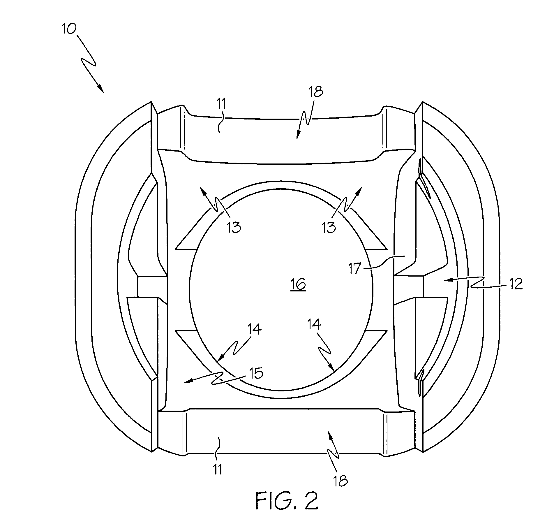
[0037]Referring initially to FIGS. 1, 2, and 3 there is illustrated rod holding element 10. As further explained herein, rod holding element 10 functions as a structure with which various components cooperate in order to create a pedicle screw assembly. Thus, in one embodiment, rod holding element 10 includes various features which are designed to cooperate with other pieces, and these features of rod holding element 10 include rod cradle 11, insert notch 12, bearing surface 13, and polyaxial head seating surface 14. The rod holding element 10 is versatile in that this single element can be used to assemble different kinds of pedicle screws including static screw, uniplanar screw, and polyaxial screw assemblies.

[0038]Rod holding element 10 is characterized by an opening 16. Opening 16 is sized such that a tip and shaft of a bone screw (not shown) can pass from an interior chamber area 15 of rod holding element 10 to the exterior of rod holding element 10. Rod holding element 10 furt...

embodiment 100

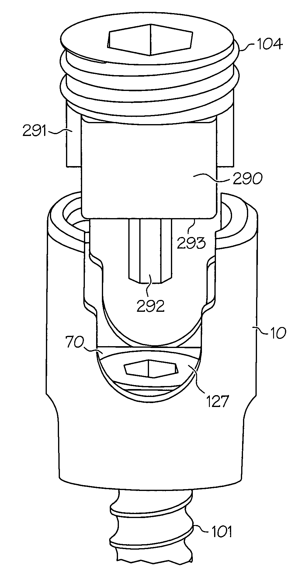
[0046]Comparing FIG. 10 to FIG. 11 illustrates further aspects of the modular pedicle screw embodiment 100. For example, it is noted that at the point of assembly in FIG. 10, rod 105 has not yet come to a final position of rest. Screw head 109 projects through insert 40, 70, and rod holding element 10 is still free to move generally along the length of screw 101. Likewise, at this point of assembly insert 40, 70 is free to move relative to rod holding element 10, as previously described. That is, a uniplanar insert 70 can move in its plane of freedom; however the monoaxial insert 40 would be restricted, because of the tab / notch fit, except to move generally upward, with respect to the orientation of FIG. 10. Rod 105 is also free to move relative to rod holding element 10. Thus, at this point of the assembly, a surgeon would typically bring the elements into alignment, as shown in FIG. 10; and then, using the freedom of movement permitted, the surgeon could make what adjustments to t...


PUM


Abstract

There is provided a modular pedicle screw assembly that includes various components which may be configured in various manners so as to provide different functionalities to the pedicle screw assembly. This advantageously decreases surgery time, reduces repetitive and tedious surgical steps, and allows for streamlining inventory of expensive medical equipment. In one embodiment, a pedicle screw assembly includes a pedicle screw, a rod holding element, an insert, a rod, and a set screw. The pedicle screw includes a threaded shaft and a cap. The rod holding element includes a screw hole, an insert bearing area, a chamber, chamber walls, a saddle area, and a threading area. The insert is disposed within the chamber, and the insert defines a bearing surface, an upper surface, side walls and a receiving area. The insert is positioned within the chamber such that the insert bearing surface contacts the rod holding element insert bearing area; additionally the side walls of the insert can bear against the chamber walls. The pedicle screw is positioned so that the screw shaft passes through the screw hold of the rod holding element and the screw cap rests within the receiving area of the insert. The rod is disposed so as to rest on the upper surface of the insert; and the set screw, joined to the threading area of the rod holding element, secures the rod to the upper surface of the insert. The insert may have a uniplanar configuration which allows movement of the insert, prior to final attachment, in a plane of motion. The insert may optionally have a monoaxial configuration which prevents movement of the insert.

Description

CROSS REFERENCE TO RELATED APPLICATIONS[0001]This application claims priority from the provisional patent application Ser. No. 60 / 903,957 filed Feb. 27, 2007, in the name of Marc C. Jacofsky and A. Joshua Appel, entitled “Modular Pedicle Screw System” incorporated herein by reference.FIELD OF THE INVENTION[0002]The present invention relates to medical devices. More particularly, the invention relates to pedicle screw systems and methods for use in spinal fixation surgeries and therapies.BACKGROUND OF THE INVENTION[0003]Spinal surgery procedures often require securing various implants to vertebrae of the spine. One such implant is the pedicle screw and its related components. Other components, such as rods, are then secured to individual pedicle screw implants in order to provide a support or fixation function between and among neighboring vertebrae. Both the rods and screws may have varying diameters and dimensions depending on patient and therapeutic needs. Due to the complex curva...

Claims


Application Information

Patent Timeline
IPC IPC(8): A61B17/04A61B17/56A61B17/58A61B17/70
CPCA61B17/7032A61B17/7082A61B17/8605A61B17/7037A61B17/7001A61B2017/681
Inventor JACOFSKY, MARC C.APPEL, A. JOSHUA
Owner THE CENT FOR ORTHOPEDIC RES & EDUCATION
Why Eureka
Try Eureka