Control apparatus of variable damping force damper

Inactive Publication Date: 2008-09-25
HONDA MOTOR CO LTD
View PDF10 Cites 22 Cited by
  • Summary
  • Abstract
  • Description
  • Claims
  • Application Information

AI Technical Summary

Benefits of technology

[0005]The present invention has been made to solve the above prior art problems, and a primary object of the present invention is to provide a control apparatus of a v

Problems solved by technology

In the above described damping force control technique, when the differentiation value of the lateral acceleration becomes large (and hence the target damping force becomes high) during a slalom run of the vehicle, for example, it becomes difficult for the damper to unde

Method used


Image

  • Control apparatus of variable damping force damper
  • Control apparatus of variable damping force damper
  • Control apparatus of variable damping force damper

Examples


first embodiment

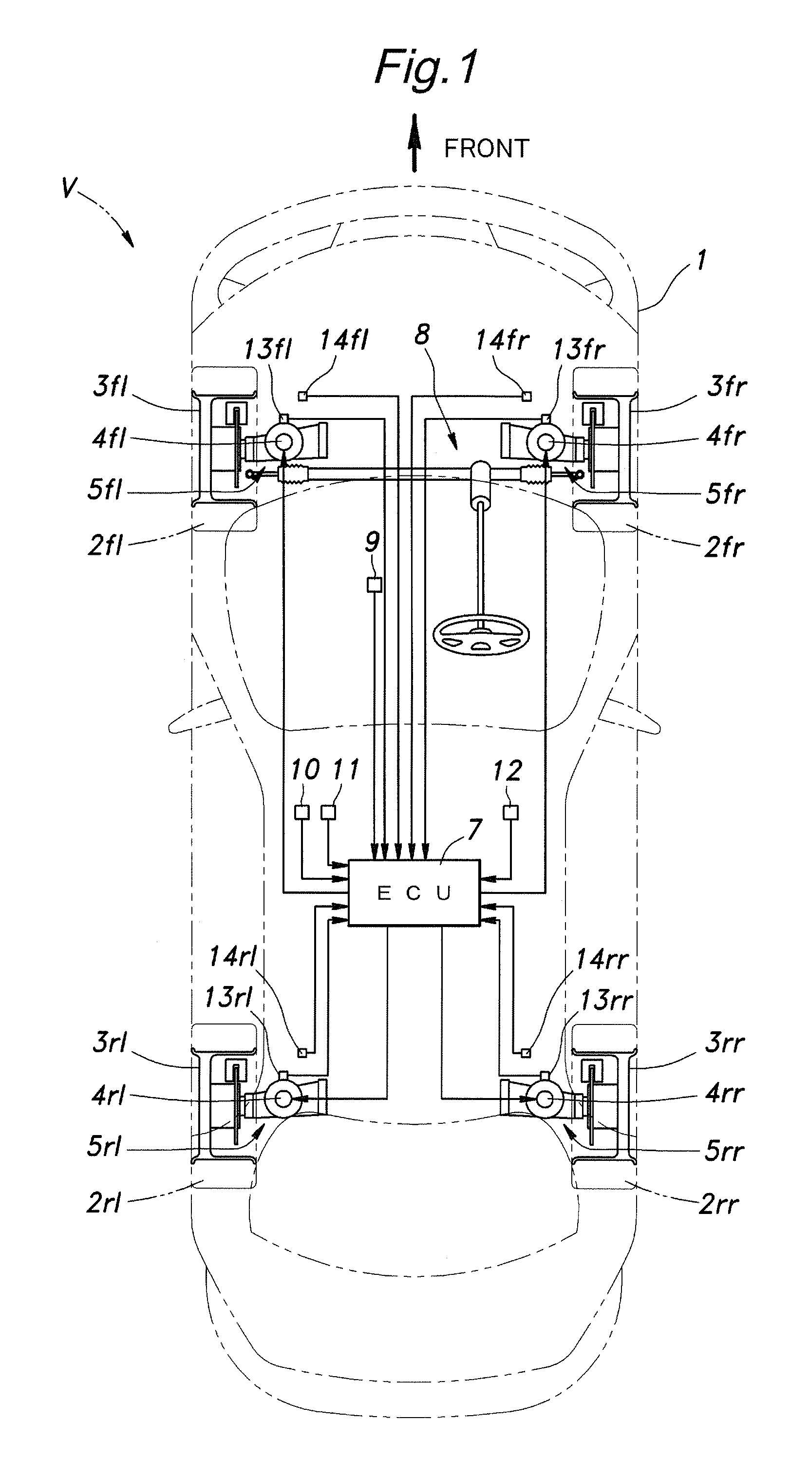
[0034]First, with reference to FIG. 1, an explanation is made to a general structure of an automobile to which the invention is applied. It should be noted that in the following explanation, reference signs designating the four wheels and devices provided therefor comprise a number followed by a pair of alphabets indicating the position thereof. For example, the front left wheel is designated with “3fl”, front right wheel is designated with “3fr”, rear left wheel is designated with “3rl”, and rear right wheel is designated with “3rr”. When referring to the wheels as a whole, only the number (3) is used such as “wheels 3”.

[0035]As shown in FIG. 1, the automobile (vehicle) V comprises four wheels 3 each of which is fitted with a tire 2, and each wheel 3 is suspended from a vehicle body 1 by means of a suspension 5 constituted by a suspension arm, spring, MRF-type variable damping force damper (simply referred to as damper, hereinafter) 4, and so on. The automobile V further comprises ...

second embodiment

[0051]Next, an explanation is made to a second embodiment of the control apparatus of a variable damping force damper according to the present invention. In the second embodiment, the structures of the automobile and variable damping force damper to which the present invention is applied may be the same as those shown in FIGS. 1 and 2, respectively, and thus detailed explanation thereof is omitted. Further, the general structure of the control apparatus of a variable control damper of the second embodiment may be the same as that of the first embodiment shown in FIG. 3 and the general flow of the damping force control process of the second embodiment may be the same as that of the first embodiment shown in FIG. 4, and thus detailed explanation thereof is also omitted.

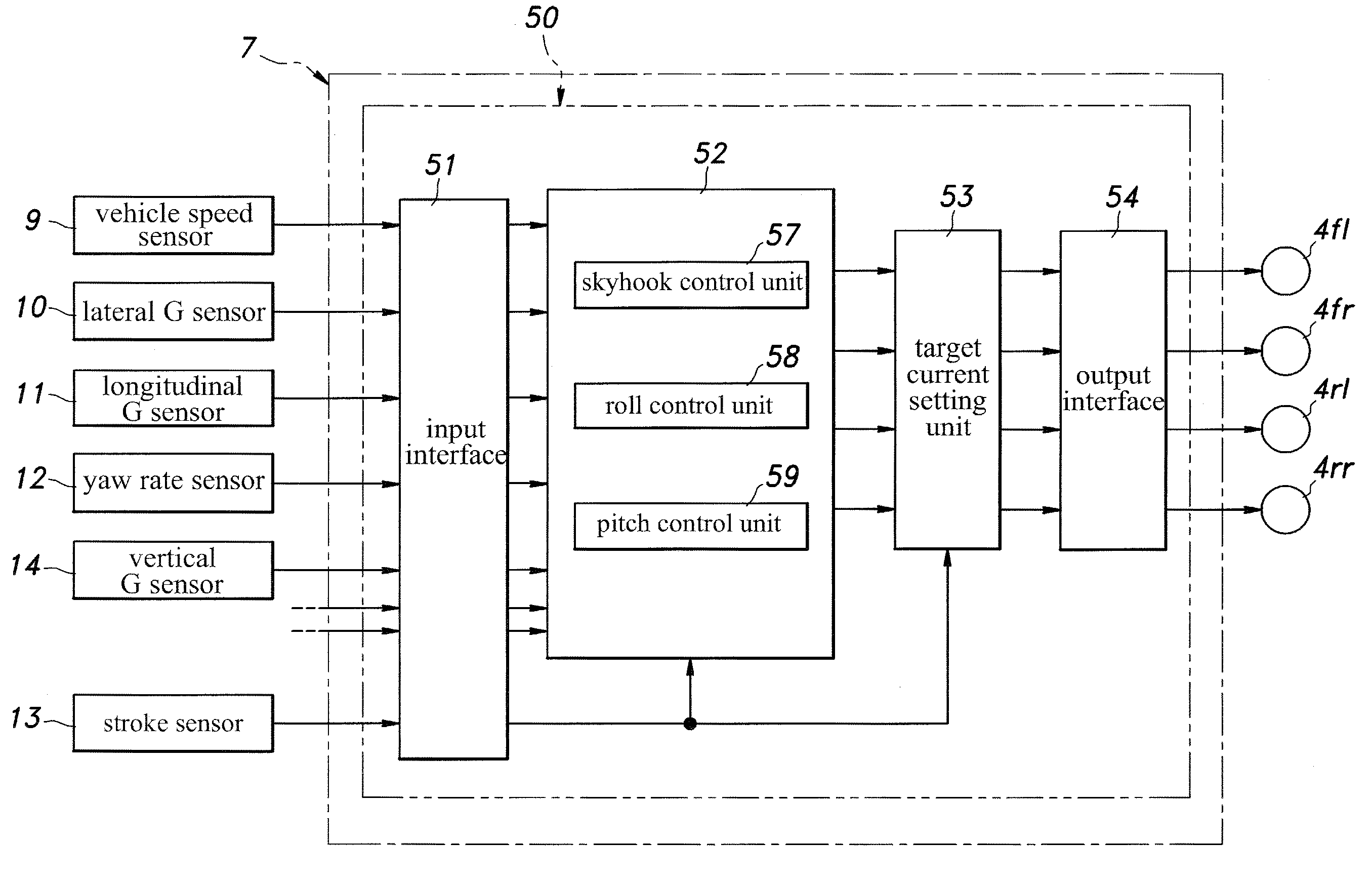
[0052]With reference to FIG. 13, in the second embodiment of the control apparatus of a variable damping force damper, the roll control unit 58 comprises, for each wheel 3: a target damping force base value setting unit...


PUM


Abstract

A control apparatus of a variable damping force damper used to suspend a vehicle body of a vehicle is configured to set a target control quantity of the variable damping force damper based on a plurality of dynamic state quantities of the vehicle, wherein the plurality of dynamic state quantities include a vertical dynamic state quantity of the vehicle.

Description

TECHNICAL FIELD[0001]The present invention relates to a control apparatus of a variable damping force damper used in a vehicle suspension system, and particularly relates to a control apparatus of a variable damping force damper that can improve riding comfort in such cases as when a vehicle is undergoing a slalom run on a road having surface irregularities.BACKGROUND OF THE INVENTION[0002]In recent years, in a field of dampers (shock absorbers) used in a vehicle suspension system, various types of variable damping force dampers that can variably control the damping force in steps or continuously have been developed. In the past, variable damping force dampers of a mechanical type were common in which a flow area of an orifice was controlled by using a motor, solenoid and the like, but in recent years, variable damping force dampers of a current control type have been developed in which a magnetic fluid or magneto-rheological fluid (MRF) is used as an operating fluid and an electric...

Claims


Application Information

Patent Timeline
IPC IPC(8): G06F17/00
CPCB60G17/018B60G17/06B60G2600/124B60G2500/10B60G2600/11B60G2400/102
Inventor KATO, TAKAFUMIKAJI, TOSHIMITSUIZAWA, MASAKI
Owner HONDA MOTOR CO LTD
Why Eureka
Try Eureka