Digital power monitoring circuit and system

Inactive Publication Date: 2008-09-25
INFINEON TECH AMERICAS
View PDF11 Cites 6 Cited by
  • Summary
  • Abstract
  • Description
  • Claims
  • Application Information

AI Technical Summary

Benefits of technology

[0015]It is an object of the present invention to provide an accurate digital power monitoring circuit that is relatively low c

Problems solved by technology

Measuring the power delivered through an inductor can be difficult in switching power supplies, however, information about the powe

Method used


Image

  • Digital power monitoring circuit and system
  • Digital power monitoring circuit and system
  • Digital power monitoring circuit and system

Examples


Embodiment Construction

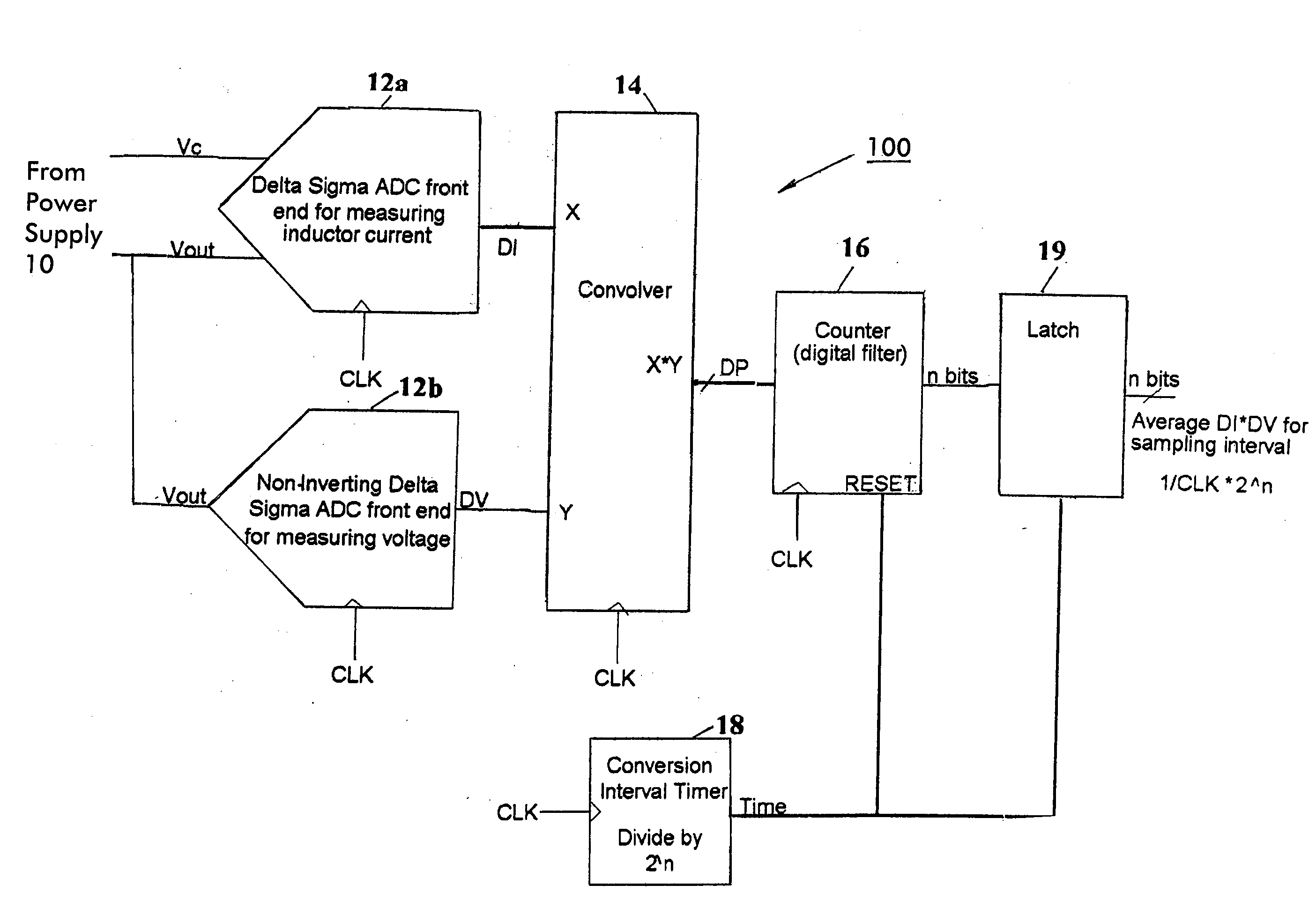
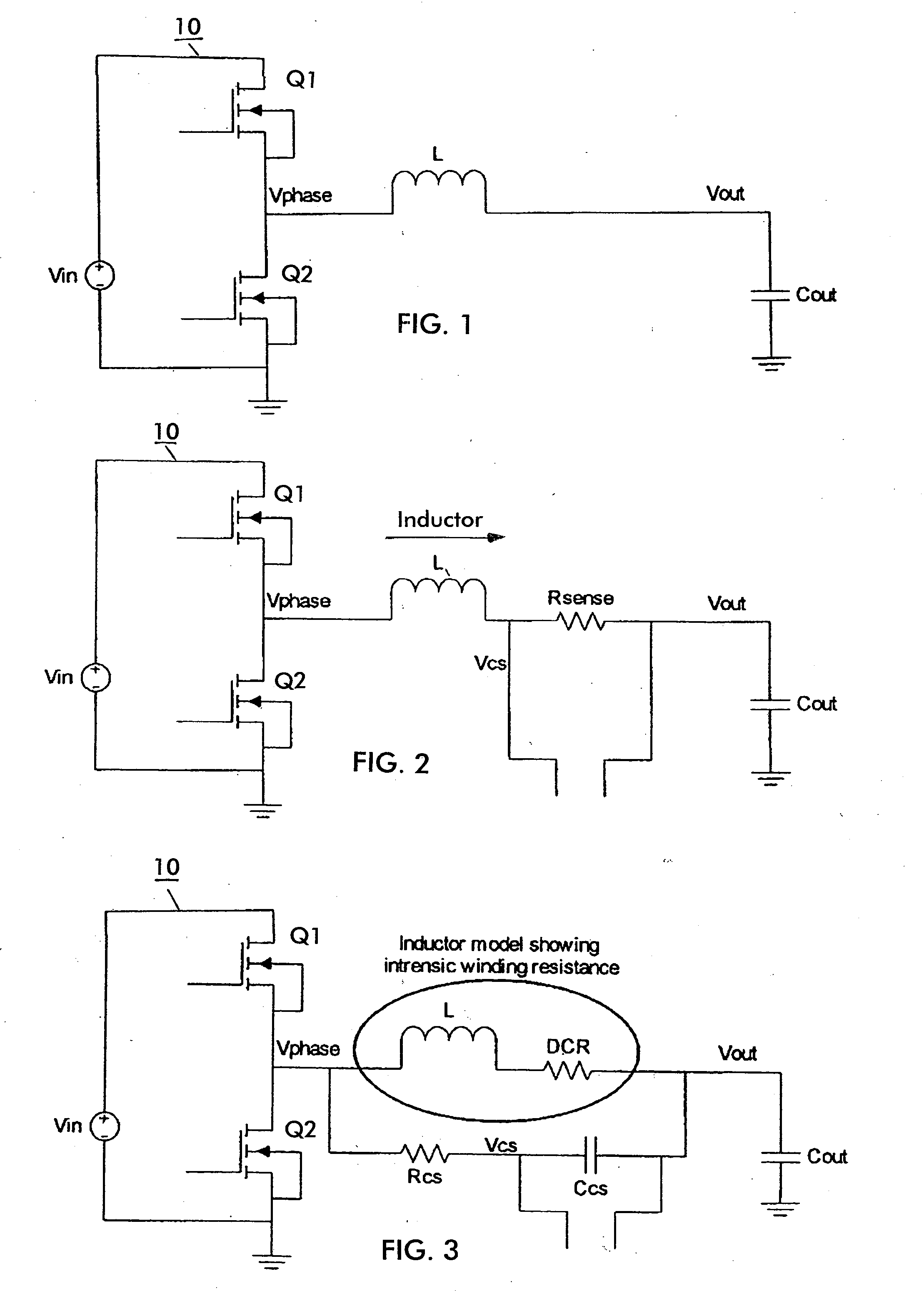
[0034]A digital power monitoring circuit 100 in accordance with an embodiment of the present application is described with reference to FIG. 7. The monitoring circuit 100 may be used to monitor the power through the output inductor L of the switching power supply 10 of FIG. 1, for example. The circuit 100 utilizes two delta sigma ADC circuits 12a, 12b to measure inductor current (Iinductor) and output voltage (Vout) of the power supply. The delta sigma ADC 12a measures current in the inductor L (Iinductor) while the second ADC 12b measures the output voltage (Vout) of the switching power supply 10. A convolver circuit 14 is provided to convolve the outputs DI, DV of the ADC's 12a, 12b, together to provide the digital signal DP which indicates the power though the output inductor L. A counter 16, an interval circuit 18 and latch 19 may be used as a digital filter to average the output of the ADC's 12a, 12b or the convolver circuit 14.

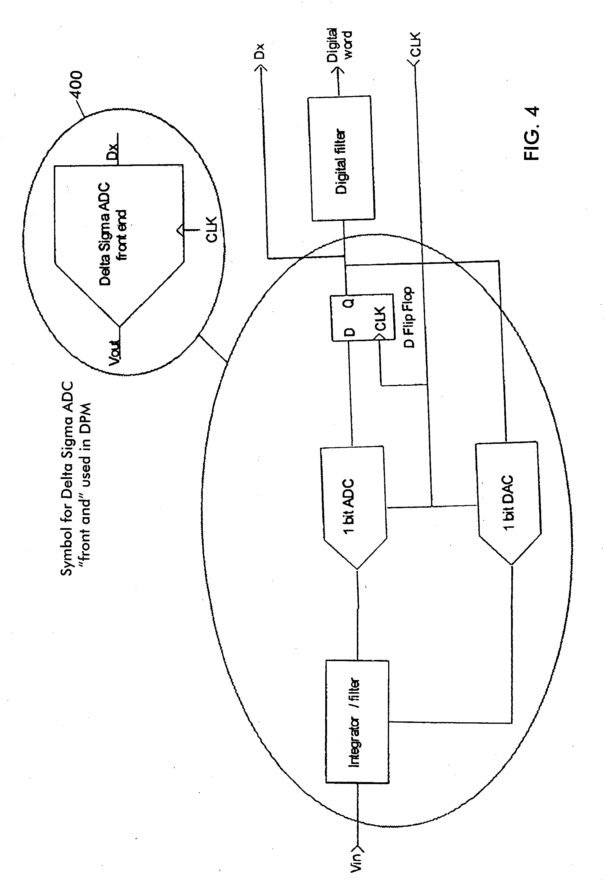
[0035]The ADC 12a may be implemented in a manner s...


PUM


Abstract

A digital power monitoring circuit for monitoring power through an output inductor of a switching power supply in accordance with an embodiment of the present application includes a first analog to digital converter receiving a current sense signal indicative of the current through the output inductor and providing a first digital signal including information regarding the current through the output inductor, a second analog to digital converter receiving a signal indicative of the output voltage of the switching power supply and providing a second digital signal containing information regarding the output voltage of the switching power supply; and a convolver circuit operable to receive the first digital signal and the second digital signal and to provide a third digital signal including information regarding the power through the output inductor based on the first and second digital signals.

Description

CROSS-REFERENCE TO RELATED APPLICATIONS[0001]The present application claims benefit of and priority to U.S. Provisional Patent Application Ser. No. 60 / 904,213 filed Mar. 1, 2007 entitled DIGITAL POWER MONITOR, the entire contents of which are hereby incorporated by reference herein.BACKGROUND[0002]1. Field of the Disclosure[0003]The present invention relates to a digital power monitoring circuit and system to provide digital power monitoring, including in a switching power supply. More specifically, the digital power monitoring circuit utilizes two delta sigma analog to digital converters (ADC) to provide first and second digital signals containing information about the current through the output inductor and the output voltage, respectively, of the switching power supply and a convolver circuit to provide a third digital signal indicating the power dissipated through the output inductor based on first and second digital signals.[0004]2. Related Art[0005]Generally, digital power mon...

Claims


Application Information

Patent Timeline
IPC IPC(8): G01R21/00
CPCG01R21/133
Inventor FORAN, RYAN
Owner INFINEON TECH AMERICAS
Why Eureka
Try Eureka