Archery bow sight

Active Publication Date: 2008-10-02
SIMS STEVEN C +4
View PDF11 Cites 10 Cited by
  • Summary
  • Abstract
  • Description
  • Claims
  • Application Information

AI Technical Summary

Benefits of technology

[0012]Also significant is the attachment of elastomeric dampers akin to those disclosed in U.S. Pat. No. 5,362,046 issued Nov. 8, 1994, to Sims to the sight at strategic locations. These dampers significantly reduce shock and vibration loads imposed on the sight when the bow is fired, contributing to accuracy and increased service life of the sight, reducing the sound made when the bow is fired, and reducing the possibility of shock and v

Problems solved by technology

This makes those ends readily visible under even extremely poor lighting conditions.
That the sight provides bright, easily seen aiming poin

Method used


Image

  • Archery bow sight
  • Archery bow sight
  • Archery bow sight

Examples


Example

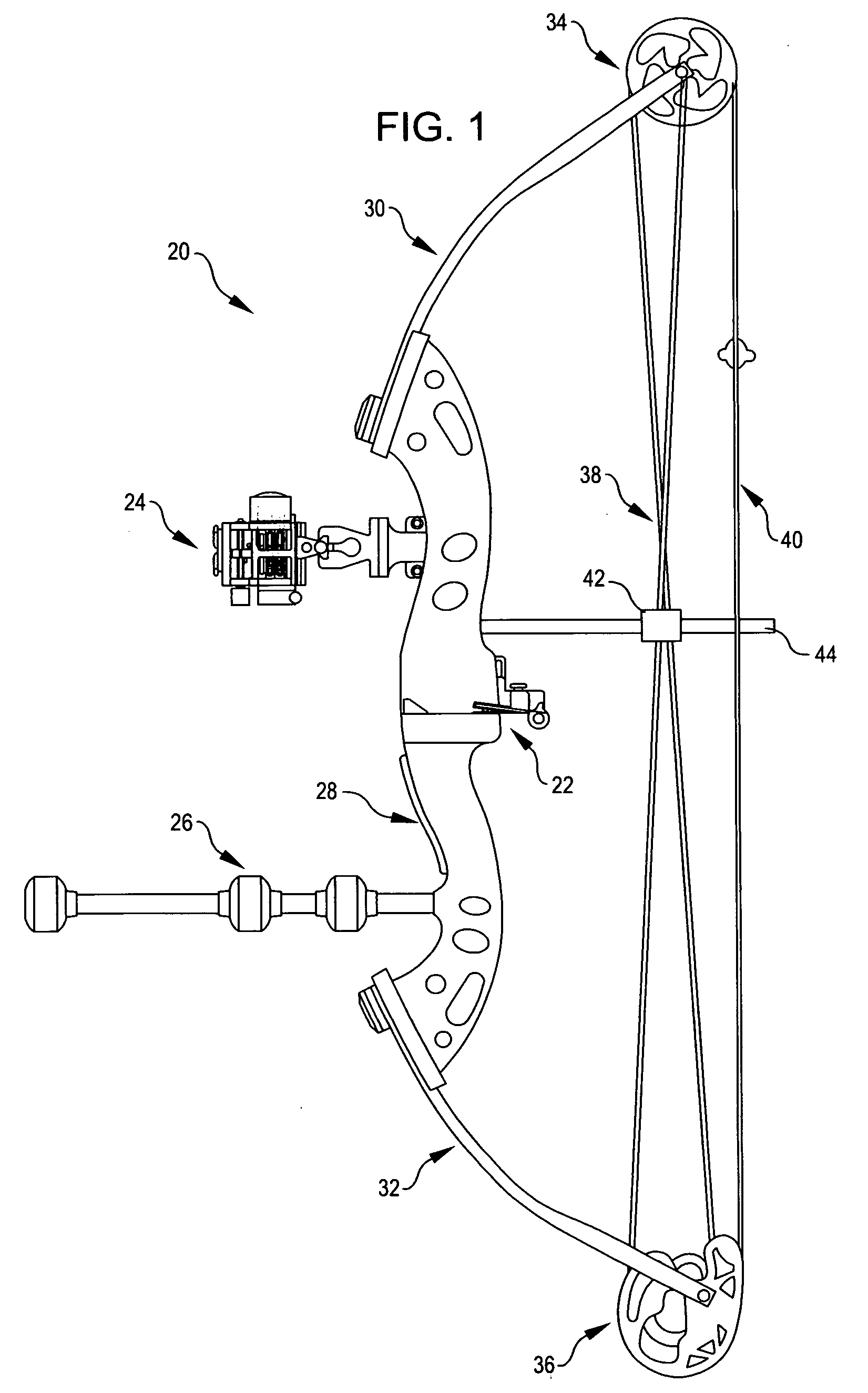
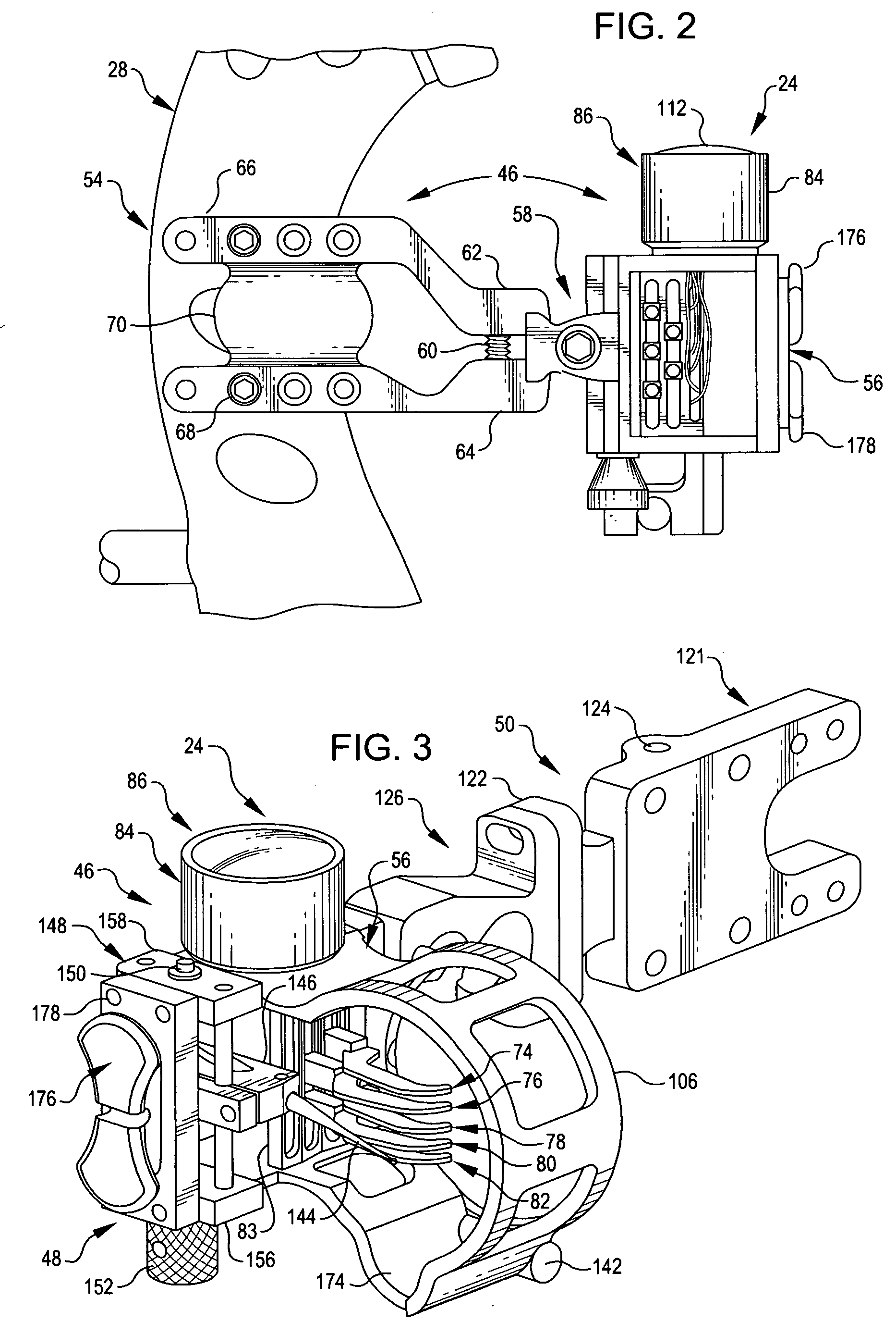
[0034]Referring now to the illustrations, FIGS. 1 and 2 depict a compound bow 20 equipped with a fall-away arrow rest 22, an optical sight 24, and a modular stabilizer 26. Bow 20 is of conventional construction. It has a riser 28, upper and lower limbs 30 and 32, cams 34 and 36 at the far ends of limbs 30 and 32, bus cables (collectively identified by reference character 38) a bow string 40, and a cable slide 42 mounted on an elongated guide 44.

[0035]Bow sight 24 includes a basic unit 46 (FIG. 2), an optional add-on or accessory 48 (FIG. 3) which provides an additional sighting capability, and a second, also optional, add-on or accessory 50. This accessory is employed to adjust torque and cant.

[0036]The basic unit 46 is assembled directly to the riser 28 of bow 20 (FIG. 2). If the torque and cant compensation accessory 50 is added, the add-on is assembled to the basic unit; and it is a mounting component of the accessory which is mounted to bow riser 28.

[0037]Referring now most part...


PUM


Abstract

An optical bow sight which can be accessorized with an adjustable range sighting pin or torque and cant compensation or both of these features, but is fully functional without either accessory. The optical sight has a shrouded array of fiber optics sight pins which are removable from the sight housing with their support as a single unit. The sight pins are clad in a metallic glass because of the corrosion resistance of such materials. Light collected over a wide field falls on segments of the sight pin fibers coiled in the housing of the optical unit or falls on a trap which redirects the light onto the fiber segments. A lens may optionally be employed to promote the collection of ambient light, and a shutter or variable size aperture may be provided to control the light reaching the sight pin fibers. An elastomeric damper can be advantageously mounted on the sight to minimize accuracy effecting shock and/or vibration, and a level bubble may be provided to aid in avoiding cant of the bow to which the sight is mounted.

Description

CROSS-REFERENCE TO A RELATED APPLICATION[0001]Applicants are entitled to and hereby claim, the priority of provisional application No. 60 / 879,944 filed 10 Jan. 2007.TECHNICAL FIELD OF THE INVENTION[0002]The present invention relates to novel, improved, archery bow sights.BACKGROUND OF THE INVENTION[0003]A common type of archery bow sight employs a set of vertically-spaced apart sight pins, each corresponding to a different range (distance to a target). These pins are installed in a frame which is mounted to the riser of the bow.[0004]In low-light conditions, those ends of the pins used for sighting can be difficult to see clearly, if at all. Accordingly, it has been proposed that the sighting ends of the pins be illuminated.[0005]One approach that has been suggested involves the use of fiber optics to illuminate the sighting ends of the pins. Sights of that character are disclosed in U.S. Pat. Nos. 5,435,068 issued 25 Jul. 1995 to Thames, et al., and 7,082,690 issued 1 Aug. 2006 to ...

Claims


Application Information

Patent Timeline
IPC IPC(8): F41G1/467
CPCF41G1/467G02B23/14
Inventor SIMS, STEVEN C.CLARK, GEORGEEASTMAN, SCOTTSEIL, JOHATHAN F.WINTERS, GREG
Owner SIMS STEVEN C
Why Eureka
Try Eureka