Dryer

a technology of drying machine and roller, which is applied in the direction of drying machine, sliding contact bearing, light and heating apparatus, etc., can solve the problems of noise, abnormally excessive abrasion of the shaft journal, and inability to finely manufacture, etc., and achieve the effect of stable suppor

Active Publication Date: 2008-10-02
LG ELECTRONICS INC
View PDF23 Cites 8 Cited by
  • Summary
  • Abstract
  • Description
  • Claims
  • Application Information

AI Technical Summary

Benefits of technology

[0017]In the drying machine, the drum

Problems solved by technology

Such a metal bearing cannot be finely manufactured, thereby causing

Method used


Image

  • Dryer
  • Dryer
  • Dryer

Examples


first embodiment

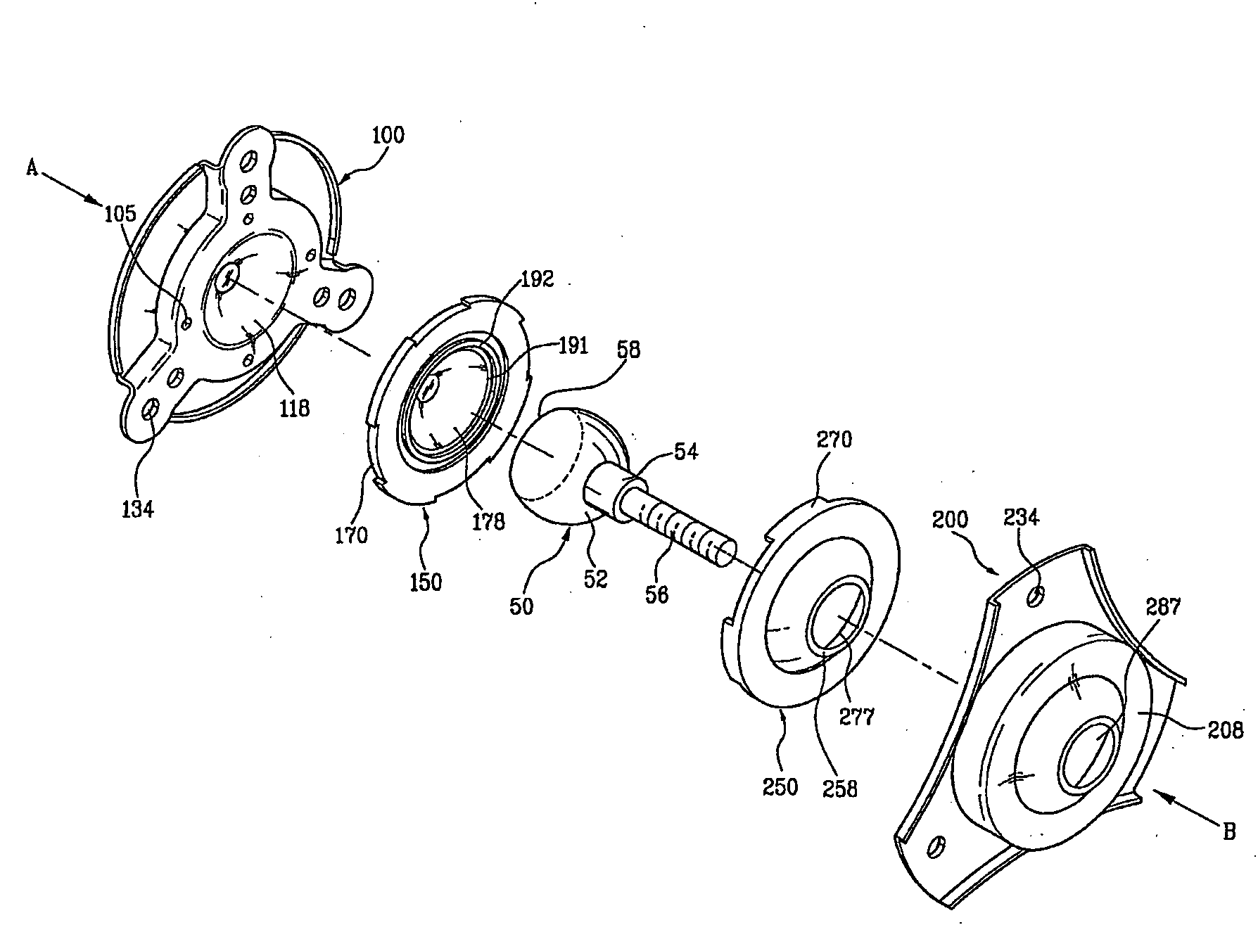
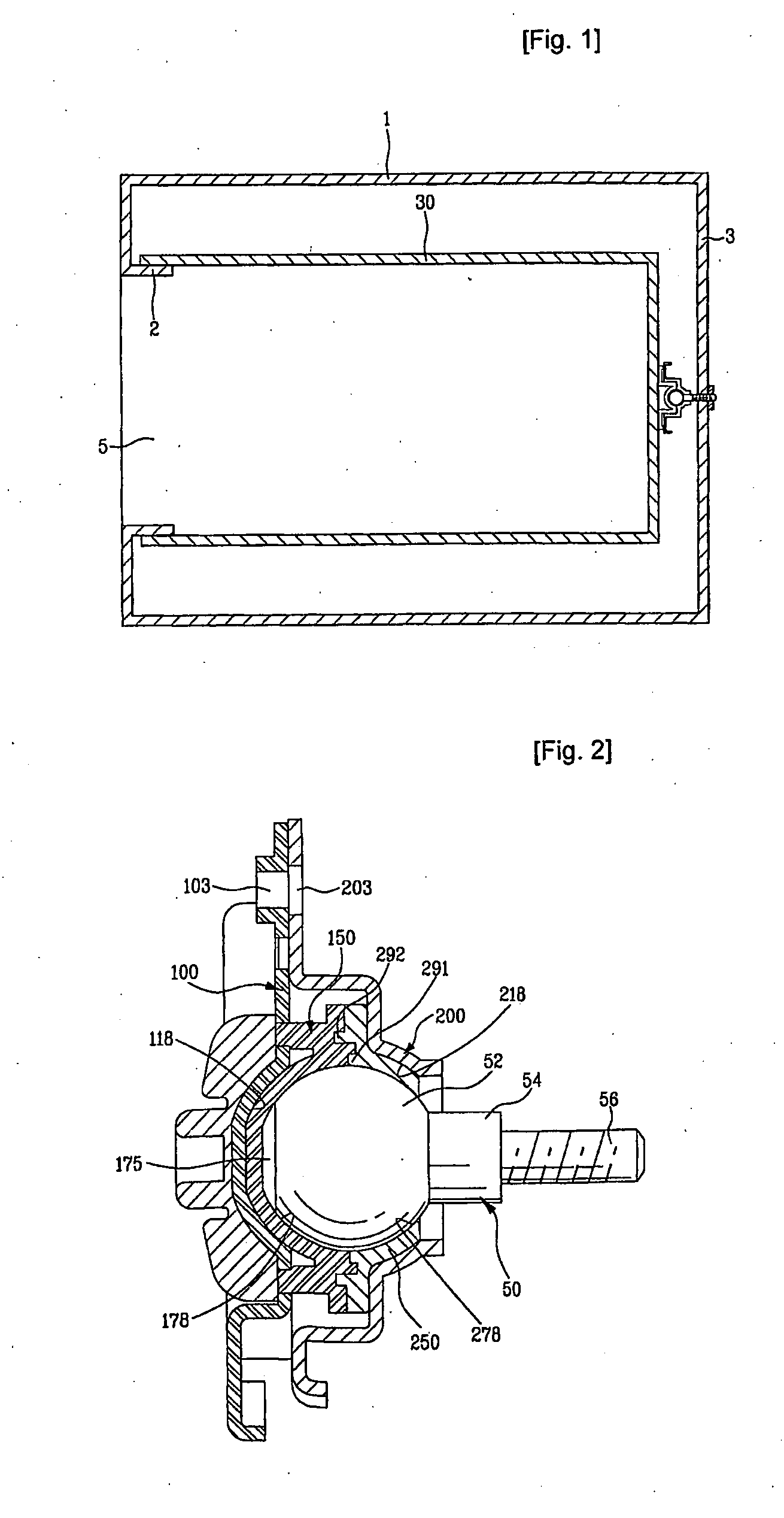
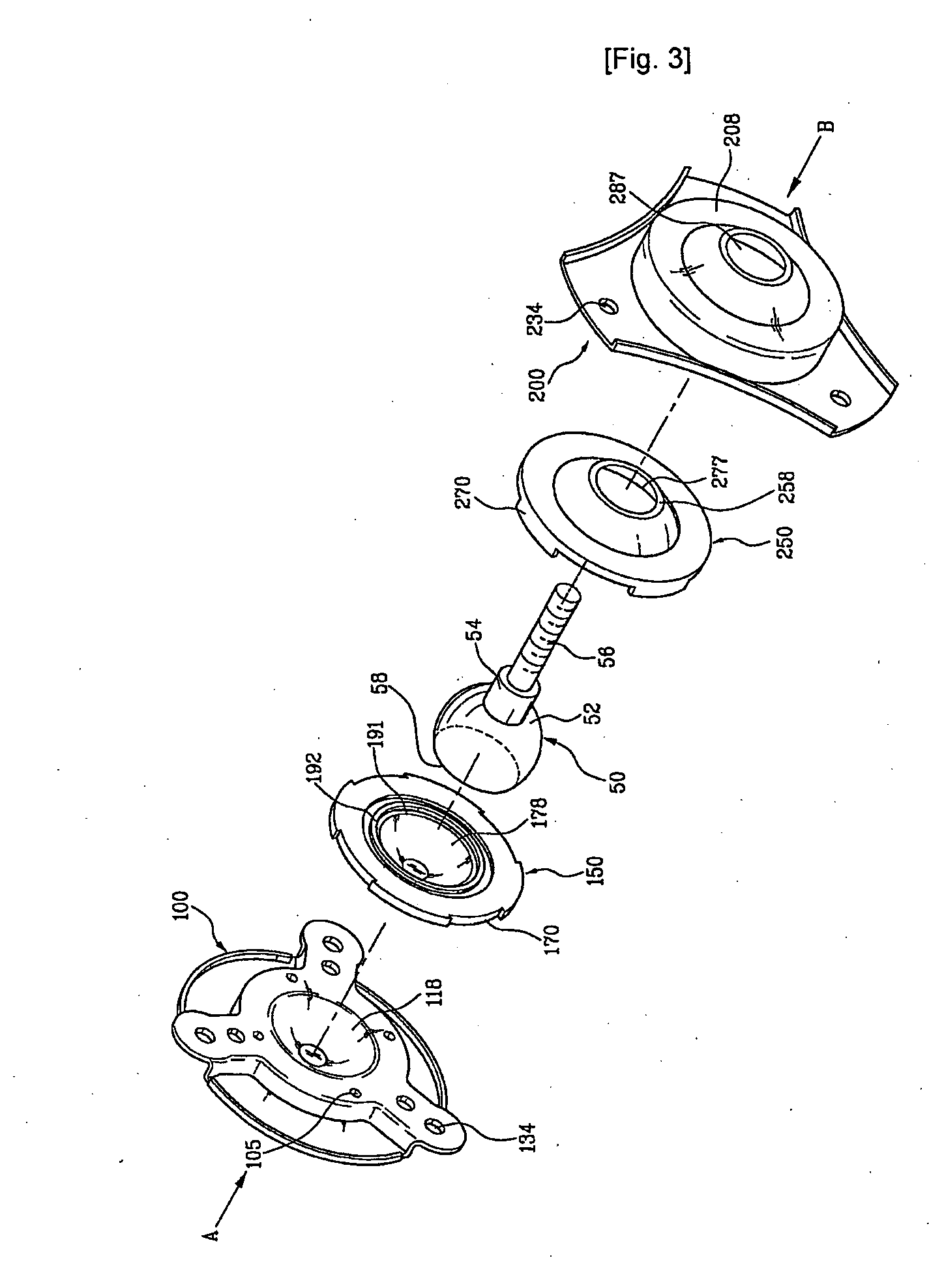
[0055]FIG. 12 is a sectional view of the modification of the bearing structure, and FIG. 13 is an exploded perspective view of the modification of FIG. 12. As shown in FIGS. 12 and 13, the modification comprises first and second bearings 300 and 400, and a shaft 50.

[0056]The first bearing 300 is connected to the drum 30 (FIG. 1), and the second bearing 400 is connected to the first bearing 300. The shaft 50, and more precisely, the journal 52 of the shaft 50, is disposed between the first bearing 300 and the second bearing 400.

[0057]With reference to FIGS. 14 and 15, the first bearing 300 comprises a boss 350 protruded from the central portion thereof, and a recess 358 formed in the boss 350 for mounting the journal 52. The first bearing 300 further comprises a plurality of connection holes 333 formed along the edge of the first bearing 300 so that the first bearing 300 is connected to the drum 30 by the connection holes 333. Preferably, as shown in FIG. 15, in order to reinforce th...

second embodiment

[0065]As shown in FIGS. 18 and 19, the bearing structure comprises a shaft 500 connected to the drum 30, a housing unit surrounding the shaft 500, and a bearing 800 installed in the first and second housings 600 and 700.

[0066]The shaft 500 comprises a flange 510 fixed to the rear surface of the drum 30, and a plurality of connection holes 501 are formed through the flange 510. The shaft 500 further comprises a journal 520 rotatably supported by the bearing 800. The shaft 500 passes through the rear surface 3 of the cabinet 1, and the journal 520 is located at the outside of the cabinet 1. Accordingly, the housing unit and the bearing 800 are disposed at the outside of the cabinet 1 so as to support the journal 520.

[0067]The housing unit comprises first and second housings 600 and 700 substantially connected to each other. The first and second housings 600 and 700 respectively comprise seats 610 and 710 for mounting the bearing 800, and connection holes 601 and 701 for connecting the...


PUM


Abstract

A drying machine in which a rotary drum is stably supported is disclosed. The drying machine includes a cabinet; a drum rotatably installed in the cabinet for containing laundry to be dried; a first housing connected to the drum; a second housing connected to the first housing; first and second bearings respectively provided in the first and second housings; and a shaft supported by the first and second bearings, and rotatably connected to the drum.

Description

TECHNICAL FIELD[0001]The present invention relates to a drying machine, and more particularly, to a bearing structure rotatably supporting a drum of a drying machine.BACKGROUND ART[0002]Generally, a drying machine is an apparatus for drying laundry using hot air generated by a heater. The drying machine comprises a drum for containing laundry, and the hot air is supplied to the drum. In order to promote the drying of the laundry, the drum is rotated preferably by a driving device, and a bearing structure for supporting a shaft of the rotating drum is provided to the drying machine.[0003]The above conventional bearing structure of the drying machine has problems, as follows.[0004]First, grease serving as a lubricant leaks from a bearing while the drying machine is being used, thereby hindering lubricating movements of the bearing and the shaft.[0005]Second, the bearing is generally made of a metal. Such a metal bearing cannot be finely manufactured, thereby causing abnormally excessi...

Claims


Application Information

Patent Timeline
IPC IPC(8): D06F58/06F16C21/00
CPCF16C11/0638D06F58/06F16C2340/00
Inventor YOON, MYOUNG KEE
Owner LG ELECTRONICS INC
Why Eureka
Try Eureka