Coupling Device

Active Publication Date: 2008-10-02
DAIMLER AG
View PDF4 Cites 10 Cited by
  • Summary
  • Abstract
  • Description
  • Claims
  • Application Information

AI Technical Summary

Benefits of technology

[0013]In a further development of the invention, a line to a cooler which is connected to a supply of a transmission lubrication system branches off from the coolant supply of the friction elements before the branching-off of the hydraulic resistance cascade. Part of the coolant flow flows via the friction elements into the transmission sump, and the other part flows via the cooler into the transmission lubrication system. This arrangement affords the advantage that no coolant which has already been contaminated with particles in the clutch enters the transmission lubrication system.
[0014]In a further development of the invention, a cooler is connected into the coolant supply line of the friction elements before the branching-off of the hydraulic resistance cascade and a line branching off which

Problems solved by technology

This risk exists in particular at very low tempe

Method used


Image

  • Coupling Device
  • Coupling Device
  • Coupling Device

Examples


Embodiment Construction

[0021]Identical components in FIGS. 1-4 are designated with the same reference numbers below.

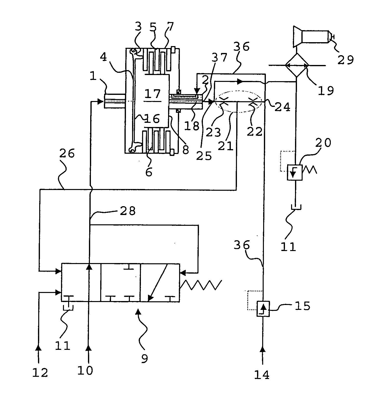
[0022]A hydraulically activatable clutch device of a transmission is illustrated diagrammatically in FIG. 1. The clutch device can be used in a hydrodynamic converter, as a lock-up clutch, or as a wet starting clutch.

[0023]The clutch illustrated in FIG. 1 connects an input shaft 1 to an output shaft 2. For this purpose, a piston 3 is provided, the first piston area 4 of which can be acted on with an operating pressure, as a result of which the piston 3 presses against friction elements 5, 6 designed as outer and inner disks. The outer disks are connected to the input shaft 1 by means of an outer-disk carrier 7, and the inner disks 6 are connected to the output shaft 2 by means of an inner-disk carrier 8. When the first piston area 4 is acted on with pressure, the friction surfaces of the inner and outer disks are pressed against one another, so that torque can be transmitted from the input s...


PUM


Abstract

A clutch device for a motor vehicle has friction elements around which coolant flows and which, by way of a piston, can be pressed against one another for torque transmission. The first piston side is acted on with operating pressure, and the second piston side is acted on with coolant pressure. A valve, by which the operating pressure can be set, and a device which makes a reaction of the coolant pressure on the operating pressure possible are provided. The device is designed as a hydraulic resistance cascade and is connected between coolant supply and coolant return lines of the friction elements. A return pressure line branches off in the center of the hydraulic resistance cascade and is connected to the valve.

Description

BACKGROUND AND SUMMARY OF THE INVENTION[0001]This invention relates to a coupling device such as a clutch device.[0002]A clutch device which has a converter with a friction clutch comprising friction elements is known from German patent specification DE 198 38 443 C1. A first side of a piston can be acted on with an operating pressure, so that the friction elements are pressed together and torque transmission takes place. Cooling oil moreover flows through the friction elements. The friction clutch is supplied with cooling oil via a supply line and a return line. A valve which delivers a corresponding operating pressure when a control pressure is specified is provided for activating the friction clutch. The pressure of the cooling oil flow acts on a second side of the piston counter to the operating pressure. In order to compensate for reactions of pressure variations on the second side of the piston on the operating pressure, the pressure present outside the clutch is at the end of...

Claims


Application Information

Patent Timeline
IPC IPC(8): F16D31/00F15B15/14F16D25/12F16D48/02
CPCF16D25/123F16D25/14F16D48/02F16D2048/0209
Inventor KEMMNER, BENJAMINSCHAEFER, ALBRECHT
Owner DAIMLER AG
Why Eureka
Try Eureka