Vibration damping device
- Summary
- Abstract
- Description
- Claims
- Application Information
AI Technical Summary
Benefits of technology
Problems solved by technology
Method used
Image

Examples
Embodiment Construction
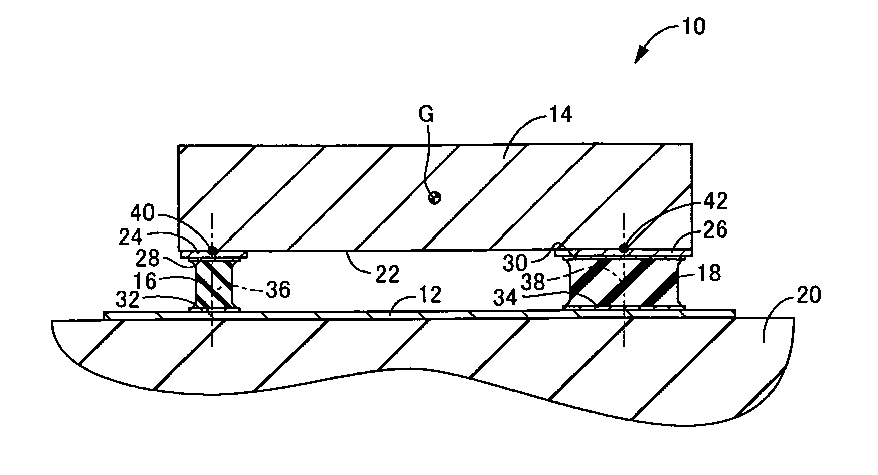
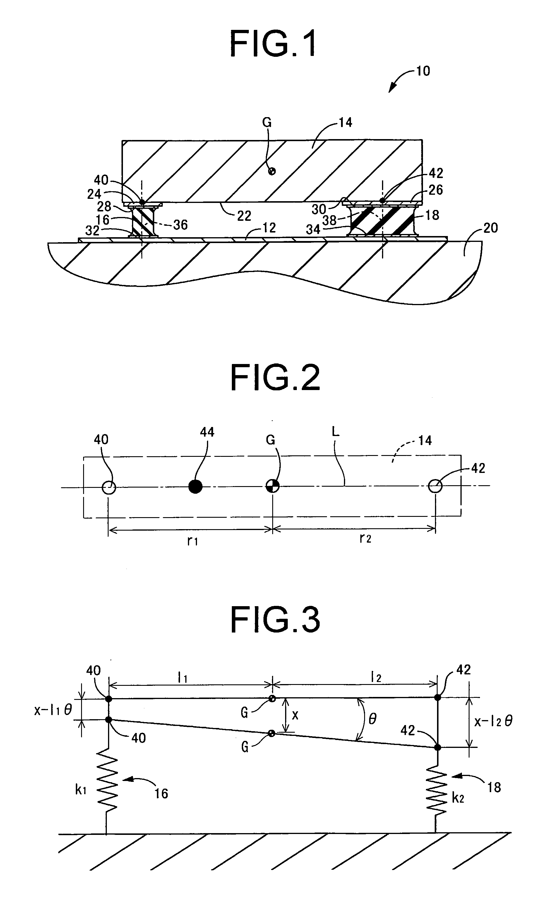
[0038]FIG. 1 depicts a dynamic damper 10 as a vibration damping device according to a first embodiment of the present invention. The dynamic damper 10 includes a mass member 14 of metal, which is elastically supported via a pair of rubber leg portions 16, 18 which constitute the rubber elastic bodies on a support plate fitting 12 which constitutes the support member. The support plate fitting 12 is attached to a vibrating member 20 such as the body frame of an automobile, with the mass member 14 elastically supported on the vibrating member 20 by the rubber leg portions 16, 18 so as to constitute a secondary vibration system for the vibrating member 20 which is the primary vibration system. In the following discussion, unless indicated otherwise, vertical direction refers to the vertical direction in FIG. 1. In the present embodiment, this vertical direction represents the plumb vertical direction, which is also the direction of input of vibration.
[0039]To describe in greater detail...
PUM
 Abstract
Description
Claims
Application Information
 - Generate Ideas
- Intellectual Property
- Life Sciences
- Materials
- Tech Scout
- Unparalleled Data Quality
- Higher Quality Content
- 60% Fewer Hallucinations
Browse by: Latest US Patents, China's latest patents, Technical Efficacy Thesaurus, Application Domain, Technology Topic, Popular Technical Reports.
© 2025 PatSnap. All rights reserved.Legal|Privacy policy|Modern Slavery Act Transparency Statement|Sitemap|About US| Contact US: help@patsnap.com