Fluid connector for garden use

a technology for fluid connectors and garden pipes, which is applied in the direction of hose connections, sleeve/socket joints, pipe joints, etc., can solve the problems of loss of the limiting function of the abutment blocks, water ingress, and water ingress of people in the sprinkler operation, so as to improve the elasticity and smooth operation the production and assembly cost of the fluid connectors can be effectively cut, and the effect of strong and durabl

Inactive Publication Date: 2008-10-02
YUAN MEI CORP
View PDF8 Cites 42 Cited by
  • Summary
  • Abstract
  • Description
  • Claims
  • Application Information

AI Technical Summary

Benefits of technology

[0008]Therefore, the primary object of the present invention is to provide an improved fluid connector for garden use wherein the sleeve is equipped with a plurality of push protrusions on the inner wall thereof that cooperate with several pair of vertical flexible ribs disposed on the periphery of a resilient retainer so that the expansion space of each pair of flexible ribs can provide a reactive force to push each inserted push protrusion backwardly so that the sleeve relieved from external force will instantly resume to its original position. Such a structure can prevent a traditional resilient retainer from being stuck due to deformation and operational fatigue when the sleeve is forced downwardly. Thus, the operation of the fluid connector become smoother in one aspect and the production and assembly cost of the fluid connector can be effectively cut down in consideration of economy of production and competition of marketing in another aspect.
[0009]Another object of the present invention is to provide an improved fluid connector for garden use wherein the resilient retainer makes use of the inner wall cavity sections of its support wall sections and stop faces and registration cavities of restraint posts to abut against the support blocks and the engagement blocks of the tube body so as to offer double build-up support to the resilient retainer to make it stronger and more durable even under great pressure produced by the sleeve pushed downwardly.
[0010]One further object of the present invention is to provide an improved fluid connector for garden use wherein the sleeve is equipped with a plurality of guide posts peripherally disposed on the inner wall thereof which are in cooperation with guide openings, slide slopes, stop posts and restraint posts of the resilient retainer so as to permit each guide post of the sleeve to slide from each restraint post along the slide slope to the stop post respectively and to be limited in place thereat without going downwardly any further. In that manner the sleeve can be firmly limited in place and a coupling pipe will not instantly get disengaged under water pressure from the fluid connector when the sleeve is accidentally pressed down, causing sprinkled water to splash all over to get people around wet.
[0011]One furthermore object of the present invention is to provide an improved fluid connector for garden use wherein the engagement blocks of the tube body are used to just engage with the registration cavities of the stop posts and the restraint posts of the resilient retainer respectively whereby the resilient retainer can be prevented from rotation along with the sleeve, making the control of the positioning of the sleeve in a more precise manner.

Problems solved by technology

Such a prior art structure of the fluid connector has the following disadvantages in practice:1. the elastic component 43 of the resilient retainer 40 is made in an arc shape and can be easily deformed under pressure as shown in FIG. 2 when the sleeve 30 is actuated by a user, resulting in the decreasing of the elasticity and the loss of the limiting function of the abutment blocks 31.
Thus, the person in operation of the sprinkler will be splashed and gets wet by accident.
Such a structure is relatively complicated and is provided with relatively too many components, making the assembly thereof difficult and time consuming in one aspect and the production cost and processing

Method used


Image

  • Fluid connector for garden use
  • Fluid connector for garden use
  • Fluid connector for garden use

Examples


Embodiment Construction

[0035]The best preferred embodiments of the present invention are hereinafter described in company with the drawings of the present invention.

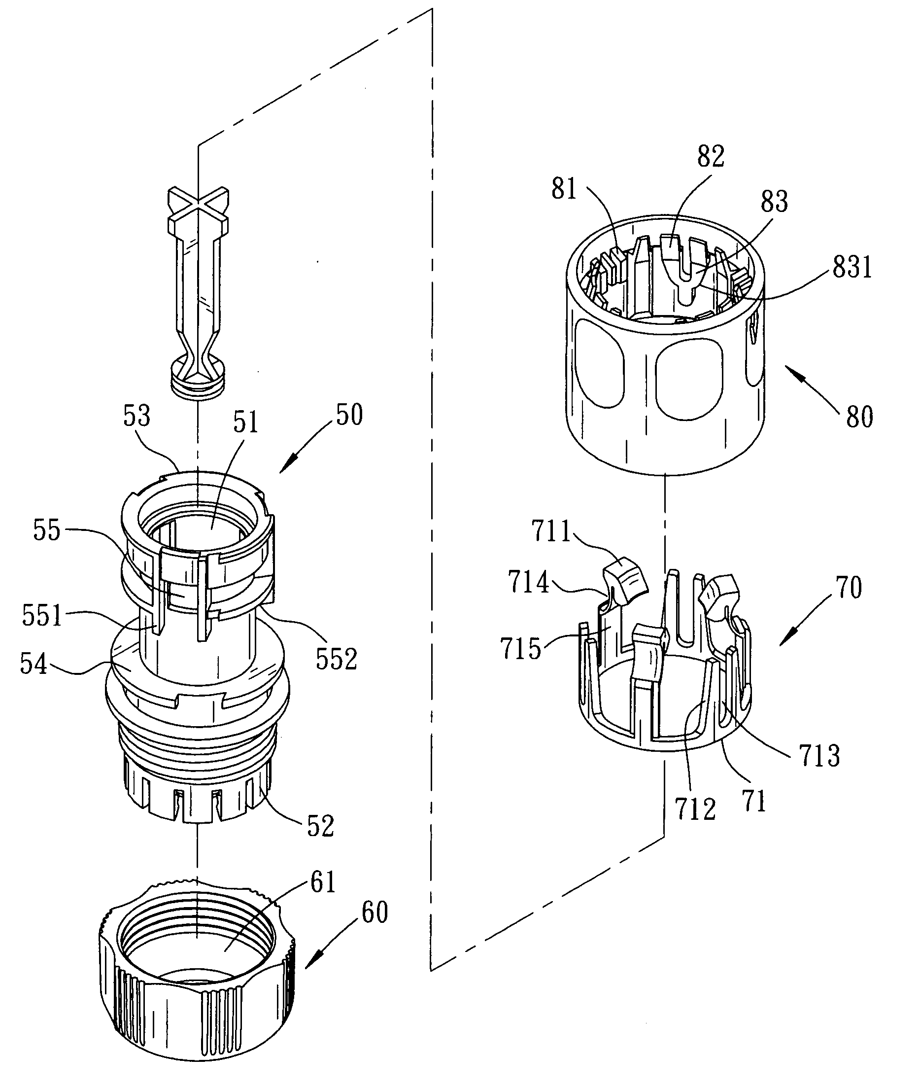
[0036]Referring to FIG. 3, which is the perspective diagram of the exploded components of the present invention, in company with FIG. 4 at the same time, it is comprised of a tube body 50, a tightening ring 60, resilient retainer 70 and a sleeve 80. The tube body 50 has an open ended flow passage 51 for flow to run through. At the end of the tube body 50 is disposed an externally threaded section with a plurality of axially extended and peripherally disposed flexible clamping dents 52 disposed next thereto so that the tightening ring 60 having an internally defined tapered section 61 can work in cooperation to clamp a tube in place. At the top end of the tube body 50 are peripherally disposed a number of sealing flanges 53. The middle of the tube body 50 is disposed a flat support periphery 54 above which are positioned a plurality of holes 55...


PUM


Abstract

The present invention relates to an improved fluid connector for garden use, which is made up of a tube body, a resilient retainer and sleeve. The tube body is provided with a plurality of holes for accommodation of a locking hook respectively and the resilient retainer is peripherally equipped with several pairs of vertical flexible ribs with an expansion space defined therebetween. On the inner wall of the sleeve are disposed a plurality of push protrusions that are positioned in relationship with the vertical flexible ribs respectively so that as the sleeve is pushed downwardly, the flexible ribs can be forced to deform and produce an reactive force that can instantly push the push protrusions of the sleeve back to their original place when the sleeve is free of an external force, making the operation of the sleeve smoother and easier without causing the resilient retainer of the conventional fluid connector to get stuck when the sleeve is pushed downwardly as a result of deformation and fatigue in operation.

Description

BACKGROUND OF THE INVENTION[0001]The present invention relates to an improved fluid connector for garden use which is made up of a tube body, a resilient retainer and sleeve. The tube body is provided with a plurality of holes for accommodation of a locking hook respectively and the resilient retainer is peripherally equipped with several pairs of vertical flexible ribs with an expansion space defined therebetween. On the inner wall of the sleeve are disposed a plurality of push protrusions that are positioned in relationship with the vertical flexible ribs respectively so that as the sleeve is pushed downwardly, the flexible ribs can be forced to deform and store an reactive force that can instantly push the push protrusions of the sleeve back to their original place when the sleeve is free of an external force, making the operation of the sleeve smoother and easier without causing the resilient retainer of the conventional fluid connector to get stuck when the sleeve is pushed dow...

Claims


Application Information

Patent Timeline
Patent Type & Authority Applications(United States)
IPC IPC(8): F16L35/00
CPCF16L25/009F16L37/091F16L37/0985F16L37/133F16L37/0982
Inventor WANG, KING YUANLO, SHUN NAN
Owner YUAN MEI CORP
Why Eureka
Try Eureka