
Switching circuit, signal output device and test apparatus

Inactive Publication Date: 2008-10-02
ADVANTEST CORP
View PDF5 Cites 1 Cited by
  • Summary
  • Abstract
  • Description
  • Claims
  • Application Information

AI Technical Summary

Benefits of technology

[0006]Meanwhile, when a voltage (for example, 2000V or more) exceeding a withstand voltage capable of being realized by FET is injected between two terminals, switching should be performed between the two terminals by means of a switching circuit that uses a mechanical relay or the like with a higher withs

Problems solved by technology

However, the mechanical relay has an extremely slow switching speed in comparison to FET.

Method used


Image

  • Switching circuit, signal output device and test apparatus
  • Switching circuit, signal output device and test apparatus
  • Switching circuit, signal output device and test apparatus

Examples


Embodiment Construction

[0020]The embodiments of the invention will now be described based on the preferred embodiments, which do not intend to limit the scope of the present invention, but just exemplify the invention. All of the features and the combinations thereof described in the embodiment are not necessarily essential to the invention.

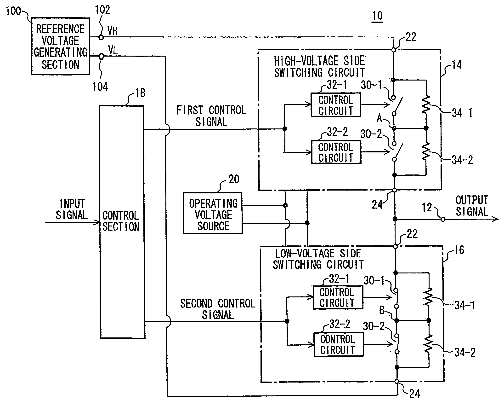
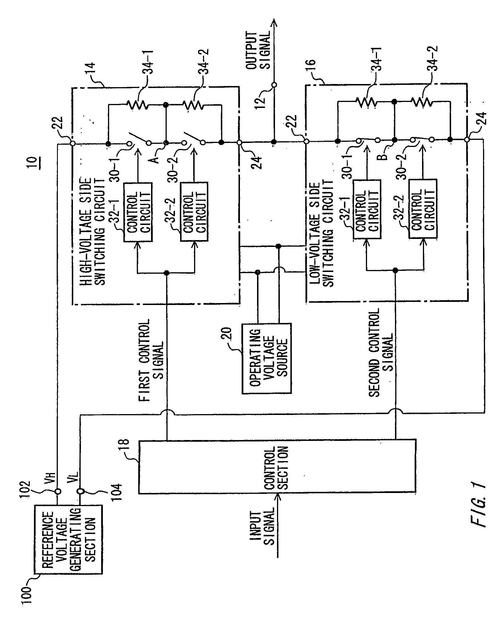
[0021]FIG. 1 shows a configuration of a signal output device 10 according to the present embodiment along with a reference voltage generating section 100. The signal output device 10 inputs an input signal expressing a logical value from an outside, and outputs an output signal according to the input signal.

[0022]The signal output device 10 is supplied with a high-voltage side reference voltage VH and a low-voltage side reference voltage VL output from the reference voltage generating section 100 provided in the outside. The reference voltage generating section 100 outputs the high-voltage side reference voltage VH from a high-voltage side reference voltage generating ...


PUM


Abstract

There is provided a switching circuit that opens or short-circuits between a first terminal and a second terminal in accordance with a control signal. The switching circuit includes a plurality of switching devices that is serially connected between the first terminal and the second terminal and each of which is opened or short-circuited in accordance with a provided control voltage, and a plurality of control circuits that is provided one-to-one corresponding to the plurality of switching devices, each of which provides a control voltage according to the control signal to the corresponding switching device, and that opens and short-circuits the plurality of switching devices in synchronization with each other.

Description

CROSS REFERENCE TO RELATED APPLICATION[0001]This patent application claims priority from a Japanese Patent Application No. 2007-088110 filed on Mar. 29, 2007 the contents of which are incorporated herein by reference.BACKGROUND[0002]1. Technical Field[0003]The present invention relates to a switching circuit, a signal output device, and a test apparatus. More particularly, the present invention relates to a switching circuit that opens or short-circuits between a first terminal and a second terminal in accordance with a control signal, and a signal output device and a test apparatus using this switching circuit.[0004]2. Related Art[0005]There has been known a FET with a high withstand voltage that can switch a high voltage (for example, 1000V). A switching circuit using such a FET can switch between two terminals, into which a voltage of several hundred volts is injected, at high speed (for example, see “Japanese Patent Application Publication 2001-284097” and “Tamotsu Inaba, Founda...

Claims


Application Information

Patent Timeline
IPC IPC(8): H03K17/00
CPCH03K17/0412H03K17/04123H03K17/163H03K17/6877H03K17/284H03K17/6871H03K17/28H03K17/00H03K17/62
Inventor AMANUMA, SEIJI
Owner ADVANTEST CORP
Learn More