Terminal equipment of electric appliance

A technology for terminal devices and electrical appliances, which is applied in the direction of fixed capacitor leads, fixed capacitor shells/packages, fixed capacitor parts, etc., can solve problems such as incomplete fixation, prevent deformation or melting, and have superior assembly process and structure simple effect

Inactive Publication Date: 2002-07-24
PANASONIC CORP
View PDF2 Cites 6 Cited by
  • Summary
  • Abstract
  • Description
  • Claims
  • Application Information

AI Technical Summary

Problems solved by technology

That is to say, the size of the small-diameter cylindrical part 26a formed by deep drawing on the upper plate 25 must be exactly the same as the size of the insulator press-in part 21a. Part 26a, is fixed incomplete

Method used


Image

  • Terminal equipment of electric appliance
  • Terminal equipment of electric appliance
  • Terminal equipment of electric appliance

Examples


Embodiment Construction

[0028] Hereinafter, embodiments of the present invention will be described with reference to the drawings.

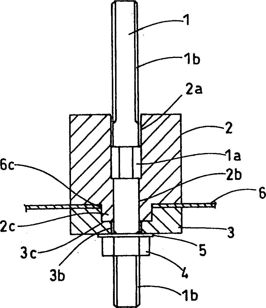
[0029] figure 1 It is a cross-sectional view of the structure of the terminal device of the first embodiment of the present invention.

[0030] The terminal device of the electric appliance in this embodiment is a capacitor terminal part, and the capacitor case 6 is a metal shell, and a plurality of capacitor elements are housed inside it. figure 1 The illustrated terminal portion is provided on the upper cover portion of the housing 6 .

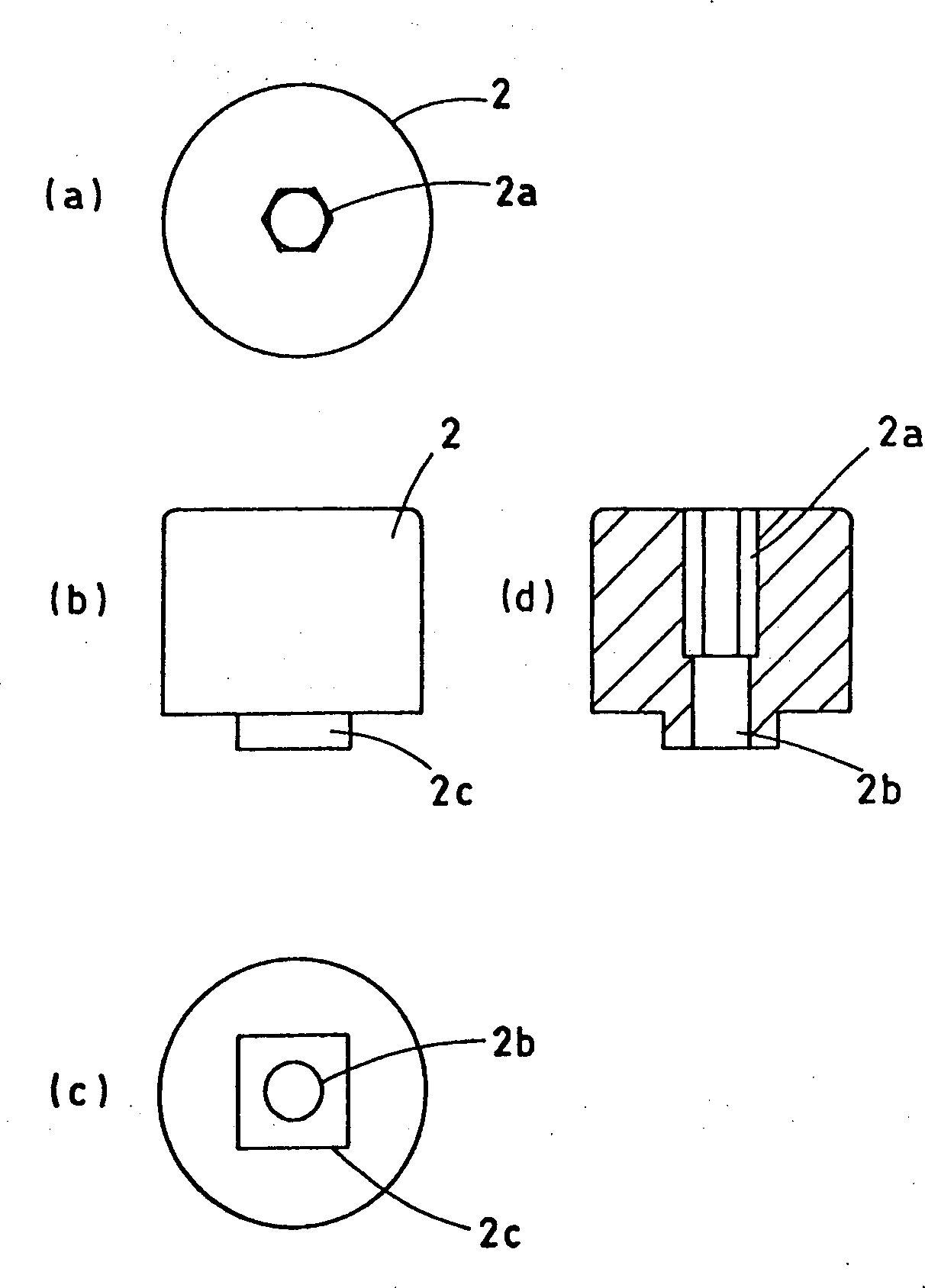
[0031] The terminal device of this electrical equipment, namely the terminal of capacitor, is contained in the loam cake of capacitor case 6 and is provided with lead-out bar 1, outer insulating terminal base 2, inner insulating terminal base 3, nut 4 and flat washer 5.

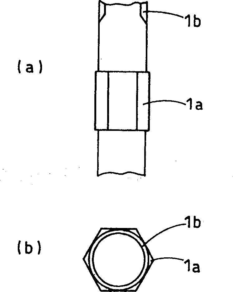
[0032] figure 2 It is a front view and a bottom view of the external lead terminal rod 1. Such as figure 2 As shown, the externally led terminal rod 1 has a...


PUM


Abstract

The present invention relates to a terminal device for an electronic apparatus, which includes an external lead out rod having a convex side part on the center; an insulation terminal seat consists of an outer insulation terminal seat and an inner insulation terminal seat, wherein one has a concave part and the other has a convex part and the two parts forms a concavo-convex part, and a counter boring for preventing the external lead out rod from rotating is formed on the outer insulation terminal seat; a casing of a through hole that the convex part of the insulation terminal seat goes into the outer terminal seat to prevent rotating; a fixing mechanism for fixing the external lead out rod on the casing through said insulation terminal seat; a concavo-convex part sets an inner terminal seat and an outer terminal seat in and out of the through hole of the casing. The terminal device is satisfactory in rotation preventing function to the rotational torque at a terminal part and is satisfactory in setup work by preventing deterioration of the functions of the terminal part, caused by human error and by making it into a structurally simple constitution, and is high in operability, and is capable of price reduction, too.

Description

technical field [0001] The present invention relates to a terminal device of an electrical appliance, in particular to a capacitor for power transmission used to improve power factor, and a terminal device for electrical appliances such as capacitors of various power lines. Background technique [0002] Conventionally, the structure of the terminal part for communicating the electric characteristics of the capacitor to the outside, such as a capacitor for power transmission, is as disclosed in KOKAI Publication No. 57-97930 and JP-KOKAI Publication No. 9-129489. [0003] refer to Figure 8-Figure 10 Describe its structure. The structure of the terminal device of the electrical parts published in the Announcement No. 57-97930 of Shikaizhao is as follows: Figure 8 as well as Figure 9 shown. exist Figure 8 and Figure 9 Among them, 11 is the metal casing of the main body of the electrical device, and what is shown in the figure is its upper cover part. 11a is an openin...

Claims


Application Information

Patent Timeline
Patent Type & Authority Applications(China)
IPC IPC(8): H01G4/224H01G4/228H01G4/236H01R9/16H01R9/18
Inventor 宇波洁草野诚松本进
Owner PANASONIC CORP
Why Eureka
Try Eureka