Compact fluorescent lamp and lighting apparatus

a fluorescent lamp and fluorescent lamp technology, applied in the direction of discharge tube luminescnet screens, energy-saving lighting, sustainable buildings, etc., can solve the problems of difficult to approach the lighting characteristic at the lighting time, difficult to obtain an outer configuration, and difficult for compact fluorescent lamps to approach the outer appearance of general lighting bulbs. to achieve the effect of reducing the non-illuminated portion of bulbs

Inactive Publication Date: 2008-10-02
TOSHIBA LIGHTING & TECH CORP
View PDF10 Cites 6 Cited by
  • Summary
  • Abstract
  • Description
  • Claims
  • Application Information

AI Technical Summary

Benefits of technology

[0012]The present invention was conceived in consideration of the above circumstances encountered in the prior art mentioned above and an object thereof is to provide a compact fluorescent lamp having an arc tube that enables minimization of a portion corresponding to the bottom portion of a conventional lighting bulb and minimization of an outer diameter of a cover of the bulb so as to possibly reduce non-illuminated portion of the bulb.
[0028]According to the above aspects of the present invention, it becomes possible to minimize a portion corresponding to the bottom portion of a lamp so as to provide a compact fluorescent lamp miniaturized up to a shape approximately identical to that of the general lighting bulb such as an incandescent lamp.
[0050]The globe is made of material such as glass and transparent synthetic resin, and means of colorless transparency, coloring, diffusion and the like may be employed according to requested properties or a reflection means such as a reflective coat may be formed partially, for example, on the globe to improve light distribution properties.
[0051]Furthermore, according to the aspects of the present invention, since the maximum outer diameter is made smaller than the maximum spiral outer diameter of the arc tube, the outer diameter of the cover member and the outer peripheral surface of the holder can be made smaller, thus realizing a small compact fluorescent lamp having a diameter decreasing toward the base as like a general incandescent bulb. In addition, a reflecting light of the arc tube is irradiated on the peripheral side wall of the cylindrical portion of the holder, and the direct light irradiated from this peripheral side wall and the surrounding portion are also illuminated, thus improving the lighting appearance.

Problems solved by technology

Because of this reason, it was difficult for the compact fluorescent lamp to approach the outer appearance of the general lighting bulb and also difficult to approach the lighting characteristic at the lighting time.
Thus, it was difficult to obtain an outer configuration such that the outer diameter reduces as being directed to the base as in the general incandescent bulb.
In addition, since the base end of the globe is apart from the base, there occupies much space of non-illuminated portion near the base, and accordingly, the lighting appearance is far from the image of the general incandescent bulb.

Method used


Image

  • Compact fluorescent lamp and lighting apparatus
  • Compact fluorescent lamp and lighting apparatus
  • Compact fluorescent lamp and lighting apparatus

Examples


first embodiment

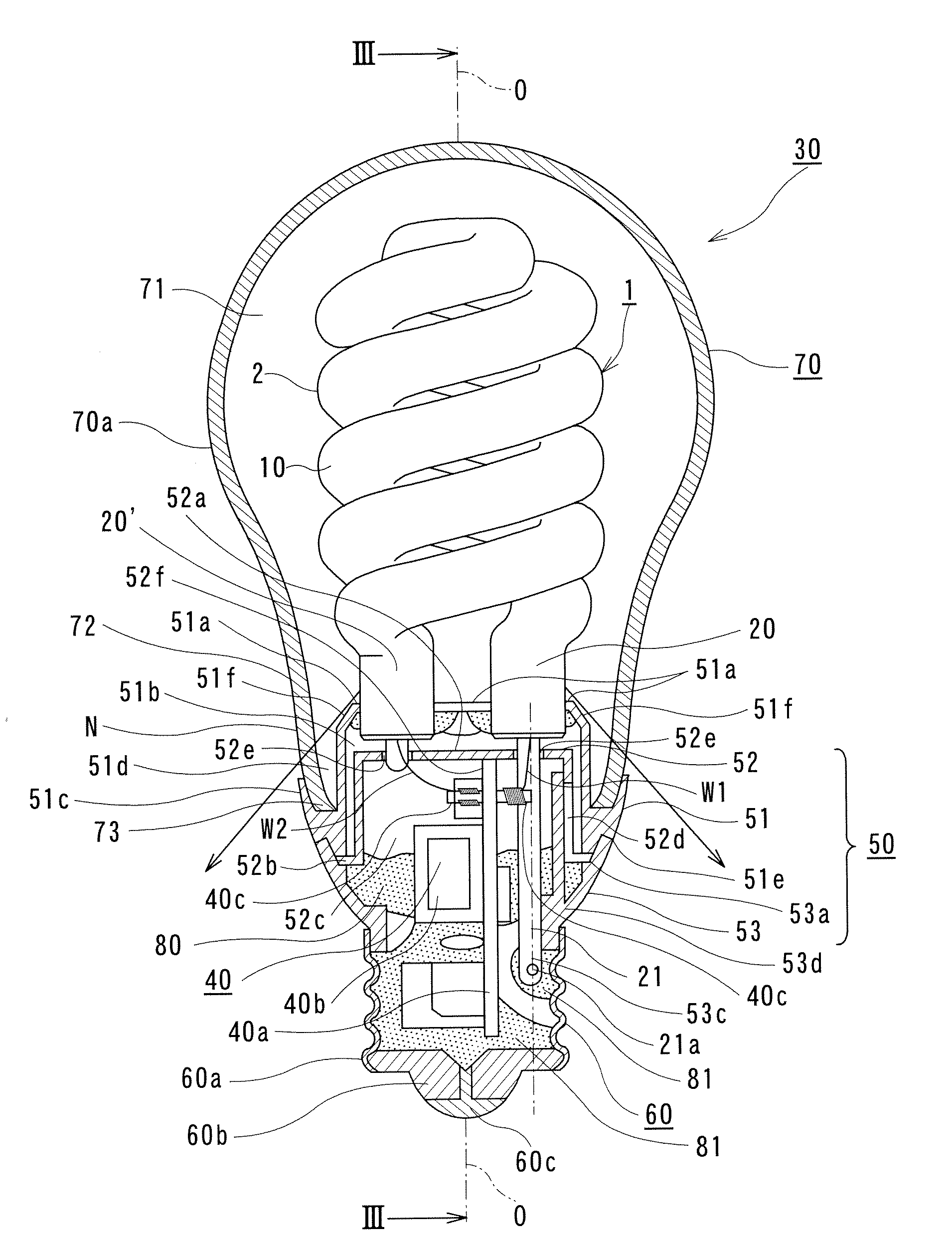
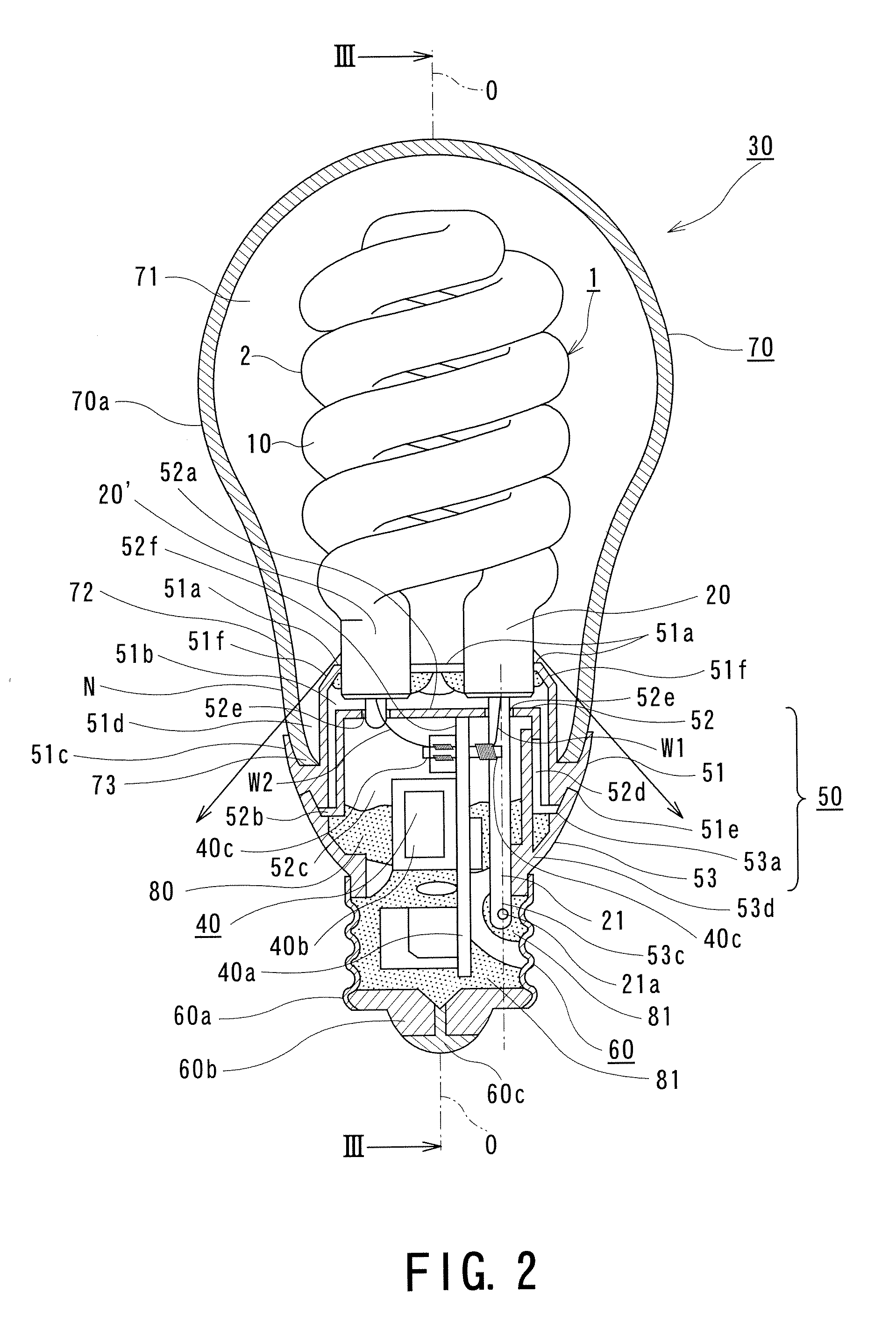
[0076]This embodiment concerns a compact fluorescent lamp (compact self-ballasted fluorescent lamp) corresponding to the incandescent lamp of 100 W type using an arc tube having a spiral portion and also concerns a downlight lighting apparatus using such lamp. First, the constitution of the arc tube will be described below.

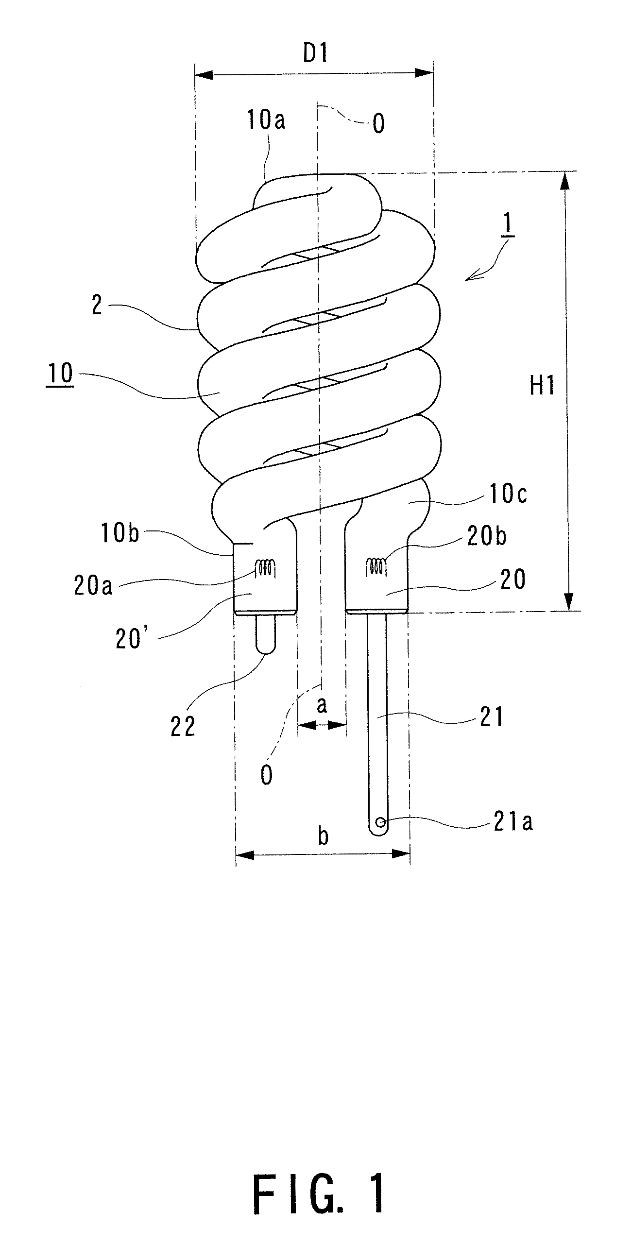
[0077]An arc tube 1 is composed of a glass bulb 2 including a spiral portion 10 and electrode sealing portions 20 and 20′ formed in both end portions of the bulb 2.

[0078]The spiral portion 10 is molded into a double spiral structure in an approximately cylindrical shape by bending a bulb made of transparent non-lead glass in a straight circular tube shape having an outer diameter of about 10 mm into two approximately equal portions in the longitudinal direction, and then, winding both end portions of the bulb 2 around a forming jig, not shown, so as to form spiral curves with an approximate center of the halved straight tubular member as a top portion 10a.

[0079]F...

second embodiment

[0177]In this second embodiment, a second inclining portion is formed by applying white resin material such as silicone resin by using a free space on the upper surface of the holder formed by setting the minimum distance “a” between the opposing inner surfaces of both the end portions of the bulb to about 10 mm.

[0178]That is, as shown in FIG. 7, the second inclining portion 51f′ is formed by applying a material having excellent thermal conductivity such as silicone resin from both the end portions of the bulb 2 to the inclining portion 51f on the upper surface of the metal holder 51 in such a way that the inclining surface descends as the outer circumference gets nearer so as to be connected with the inclining portion. The upper surface of the holder is subjected to radiation measure.

[0179]Therefore, the heat of the arc tube 2 can be more easily transmitted to the holder 51.

[0180]The light emitted from the arc tube 1 is reflected by a white inclining surface made of silicone resin ...

third embodiment

[0196]The third embodiment of the present invention will be described hereunder with reference to FIGS. 10 to 13.

[0197]With reference to FIGS. 10 to 12, a reference numeral 111 denotes a compact (self-ballasted) fluorescent lamp according to the third embodiment of the present invention.

[0198]The compact fluorescent lamp 111 includes a cover 113 having a base 112 at one end in a height direction, an arc tube 114 supported by the other end of the cover 113, a holder 115 made of metal mounted on the other end of the cover 113 supporting one end of the arc tube 114, a partition plate 116 made of synthetic resin provided so as to cover an inner surface of the holder 115, a globe 117 mounted on the holder 115 so as to cover the arc tube 114, and a lighting device 118 housed inside the base 112, cover 113 and holder 115.

[0199]As described above with reference to the first and second embodiments of the present invention, the outer appearance of this compact fluorescent lamp is formed appro...


PUM


Abstract

A compact fluorescent lamp includes an arc tube having a bulb with a spiral portion formed in at least a portion thereof, the bulb having an electrode sealed in each of both end portions thereof so as to form a discharge path inside, and both the end portions of the bulb opposing to each other at positions inside a portion having a maximum outer diameter of the spiral portion so that the opposing end portions have a minimum distance of 5 to 15 mm; a lighting device lightening the arc tube; a cover member which supports the arc tube and in which the lighting device is arranged; and a base supported by the cover member.

Description

BACKGROUND OF THE INVENTION[0001]1. Field of the Invention[0002]The present invention relates to a compact fluorescent lamp (or compact self-ballasted fluorescent lamp) including an arc tube which is capable of being substituted for an existing general lighting bulb and also relates to a lighting apparatus using the compact fluorescent lamp.[0003]2. Related Art[0004]There is known a compact fluorescent lamp in which a holder is provided at a base mounted to a socket of a general lighting bulb such as an incandescent lamp and in which an arc tube formed by bending a glass tube bulb and a lighting device are mounted in the holder. The arc tube is covered with a globe.[0005]In recent years, there has been proposed a compact fluorescent lamp for increasing a length of discharge path by forming an arc tube arranged in a narrow space inside the globe into a spirally bending shape so as to achieve miniaturization and realize higher output of the lamp, for example, as shown in Patent Public...

Claims


Application Information

Patent Timeline
Patent Type & Authority Applications(United States)
IPC IPC(8): H01J1/62
CPCH01J61/327Y02B20/19Y02B20/00
Inventor NAGASAWA, KIMIYOSHIYASUDA, TAKEOKUBOTA, HIROSHIHAKUTA, SHINYAIKADA, KUNIHIKOONO, TETSUYAIKEDA, TOSHIYUKI
Owner TOSHIBA LIGHTING & TECH CORP
Why Eureka
Try Eureka