Feedback controller having multiple feedback paths

Active Publication Date: 2008-10-02
HONG KONG APPLIED SCI & TECH RES INST
View PDF7 Cites 41 Cited by
  • Summary
  • Abstract
  • Description
  • Claims
  • Application Information

AI Technical Summary

Benefits of technology

[0012]Preferably, the feedback controller further comprises a switch coupled to the comparator for being turned on and off by the feedback controller. The switch may control the output voltage of a switch mode power supply.
[0013]There is also disclosed herein a pulse width modulation (PWM) control circuit for a switch mode power supply comprising a switching circuit, a low bandwidth feedback circuit and a high gain high bandwidth feedback circuit. The switching circuit has an error node and controls a duty-cycle of a switch in response to an error signal at an error node. The low bandwidth feedback circuit is connected to the switch mode power supply output for sensing a portion of an output signal of the switch mode power supply and generating a first error signal at the error node. The high gain high bandwidth

Problems solved by technology

Controllers having a high bandwidth react quickly to large changes in the output but can be difficult to stabilize especially in noisy environments or in power supply supplying quickly changing loads.
While all

Method used


Image

  • Feedback controller having multiple feedback paths
  • Feedback controller having multiple feedback paths
  • Feedback controller having multiple feedback paths

Examples


Embodiment Construction

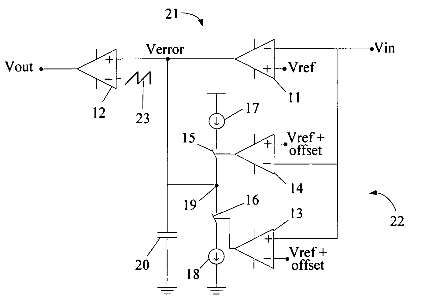
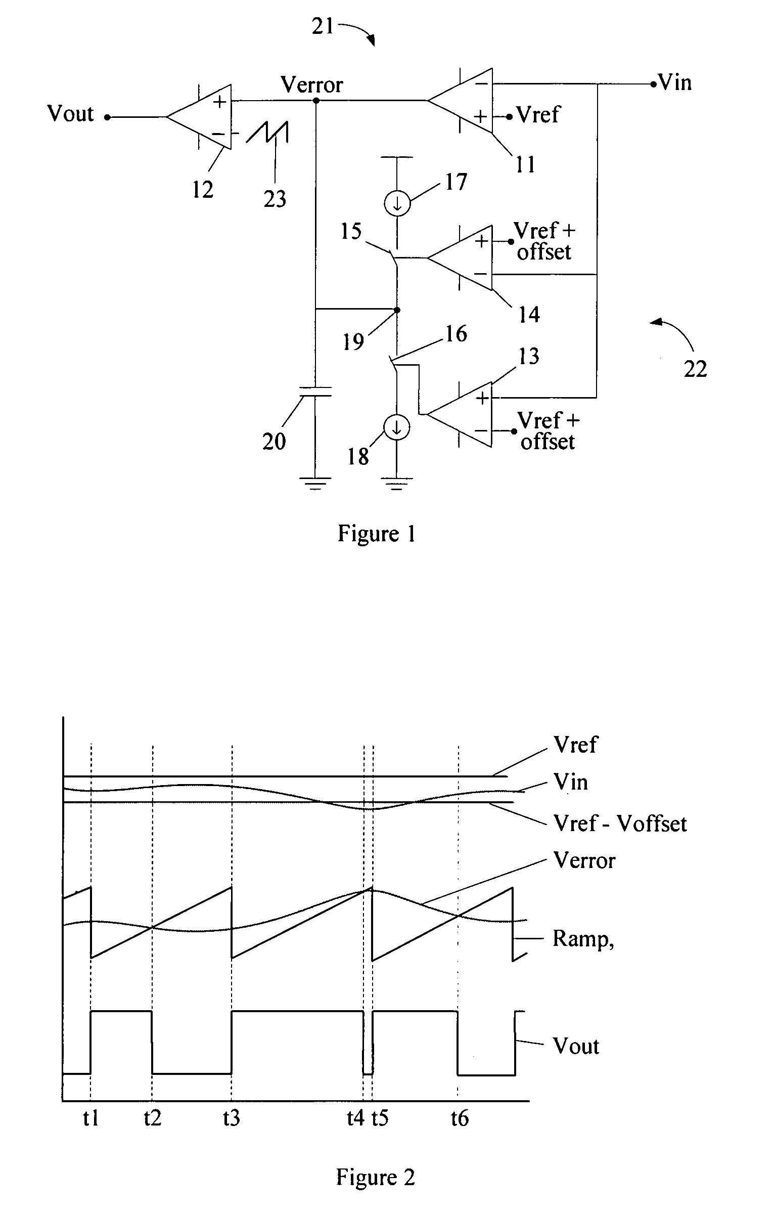
[0025]FIG. 1 of the drawings shows a feedback controller 10 according to the invention which comprises an input node Vin an output node Vout and two feedback paths 21, 22. The first feedback path is connected between the input nodes Vin and output Vout and includes a low bandwidth and high gain differential amplifier 11 and a comparator 12 coupled together at an error node Verror. The differential amplifier 11 compares a feedback signal input at input node Vin with a reference voltage Vref. The output of the differential amplifier 11 is an error signal at the error node Verror. The comparator 12 compares the error signal with a periodic ramp, or sawtooth, reference signal 23. When the value of error signal is greater than the value of the ramp signal 23 the comparator output goes as high as possible and when the value of the error signal is less than the value of the ramp signal 23 the output of the comparator 12 goes as low as possible. The output of the comparator 12 is coupled to...


PUM


Abstract

A feedback controller comprises first and second feedback circuits. The first feedback circuit is connected between an input node and an output node and has an error node. The first feedback circuit comprising a feedback amplifier for comparing a feedback signal to a reference signal and providing an error signal, and a comparator for comparing the error signal to a second reference signal and providing an output signal. The second feedback circuit is connected between the input node and the error node and comprises a current source coupled to the error node and a controller coupled to the input node for controlling the current source in response to a value of the feedback signal being above or below a threshold value.

Description

BACKGROUND TO THE INVENTION [0001]1. Field of the Invention[0002]The current invention relates to a feedback controller having multiple feedback paths. Particularly, although or exclusively, the current invention also relates to a feedback controller having multiple feedback paths which can be used as a pulse width modulation control circuit for a switch mode power supply.[0003]2. Background Information[0004]Pulse width modulation control circuits are well known and are widely used in switch mode power supplies. A typical controller has a feedback path that compares a sample of the power supply output with a referenced voltage and generates an error signal for a PWM control circuit that varies the duty cycle of the power supply switching device in response to the value of the error signal. As with all control systems there is a trade-off of between stability and response time. Controllers having low bandwidth always provide very stable control characteristics, but react slowly to la...

Claims


Application Information

Patent Timeline
IPC IPC(8): G05F1/10H03K5/153
CPCH03F3/217H03F3/45475H03K7/08
Inventor NG, CHIK WAIWONG, YAT TOKWONG, DAVID KWOK KUEN
Owner HONG KONG APPLIED SCI & TECH RES INST
Why Eureka
Try Eureka