Waveguide Corner and Radio Device

a radio device and corner technology, applied in waveguide devices, basic electric elements, electrical devices, etc., can solve the problems of low layout freedom of waveguide microwave circuits in which a plurality of waveguides are combined, and the waveguide circuit becomes larger, so as to increase the degree of freedom of layout of radio devices and reduce the effect of device siz

Inactive Publication Date: 2008-10-02
MURATA MFG CO LTD
View PDF5 Cites 20 Cited by
  • Summary
  • Abstract
  • Description
  • Claims
  • Application Information

AI Technical Summary

Benefits of technology

[0004]The present invention has been made in consideration of the above-described problem of the related technology, and it is an object of the present invention to provide a waveguide corner and radio device in which the degree of freedom of layout of a waveguide circuit is increased and the waveguide circuit can be made smaller.

Problems solved by technology

As a result, according to the related technology, the freedom of layout of a waveguide microwave circuit in which a plurality of waveguides are combined is low and there is a problem in that the waveguide circuit becomes larger.

Method used


Image

  • Waveguide Corner and Radio Device
  • Waveguide Corner and Radio Device
  • Waveguide Corner and Radio Device

Examples


second embodiment

[0059]Next, FIGS. 4 to 7 show the present invention. The second embodiment is characterized in that the H-plane wall of the second rectangular waveguide constitutes the same plane as the E-plane wall of the first rectangular waveguide.

[0060]Reference numeral 11 denotes a waveguide corner according to the second embodiment. The waveguide corner 11 includes rectangular waveguides 12 and 14 to be described later, and the rectangular waveguides 12 and 14 are connected in a bent state.

first embodiment

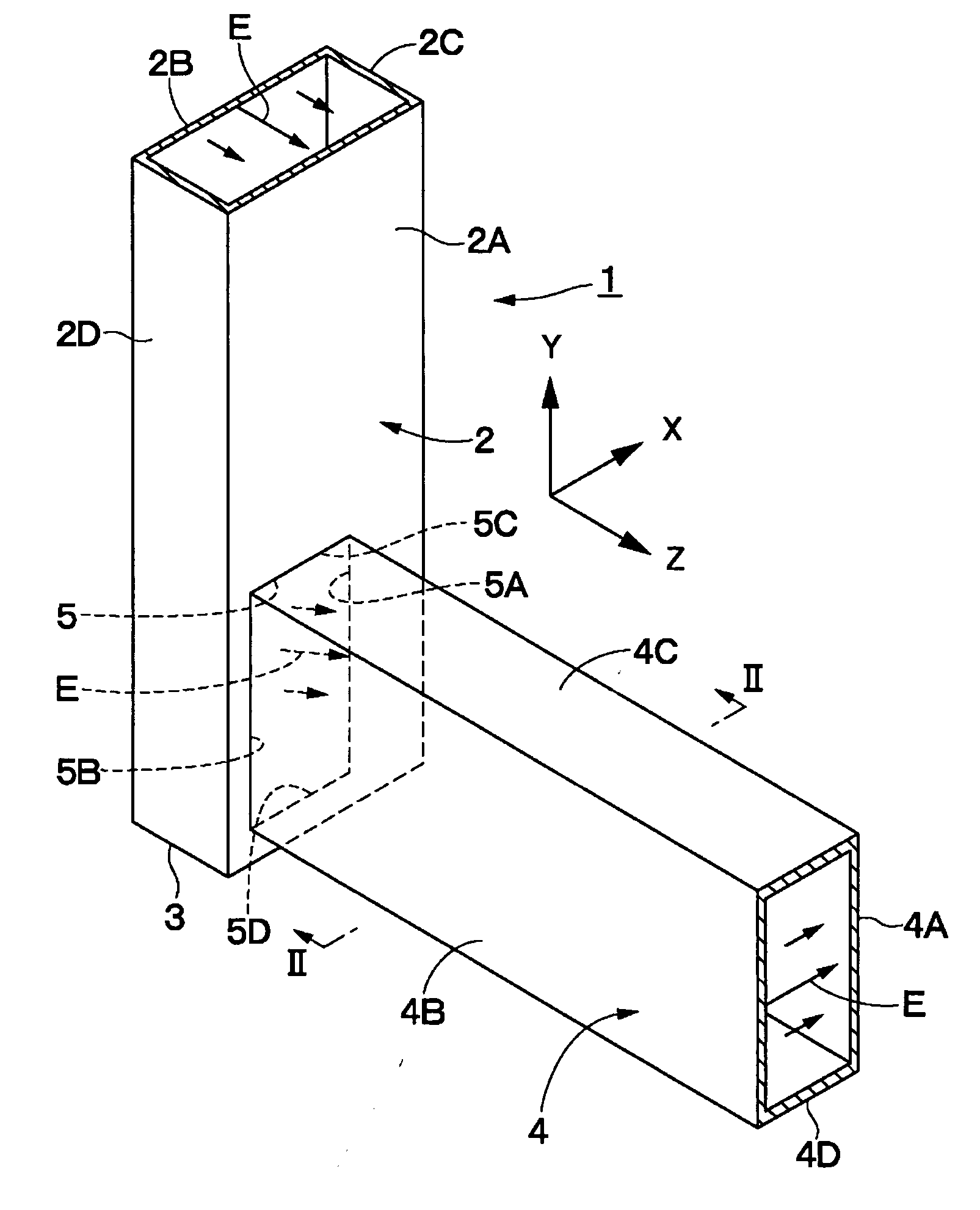
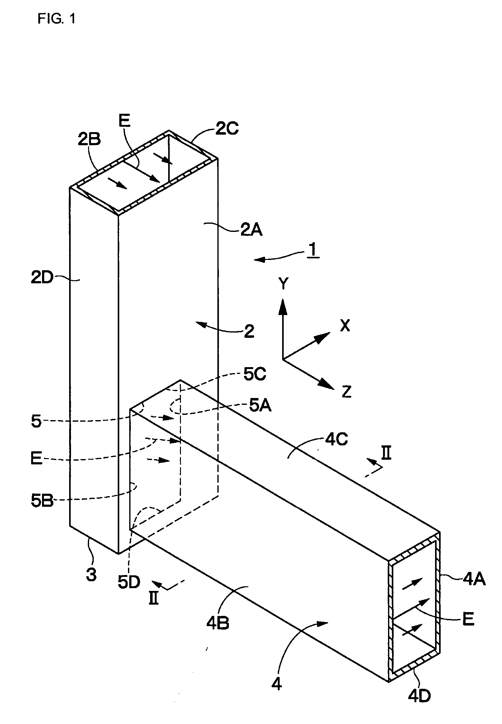
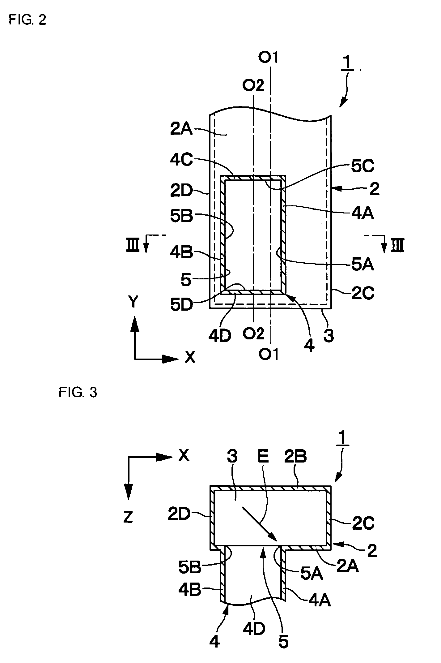
[0061]Reference numeral 12 denotes a first rectangular waveguide (H-plane waveguide) consisting of a rectangular hollow conductor pipe in which the pipe axis extends in the Y-axis direction, for example. The rectangular waveguide 12 is formed so as to be rectangular in section by a pair of H-plane walls 12A and 12B, opposite to each other, having a long longitudinal dimension (dimension in the X-axis direction) perpendicular to the pipe axis and E-plane walls 12C and 12D having a short transverse dimension (dimension in the Z-axis direction) and positioned at both ends of the H-plane walls 12A and 12B for connecting the pair of H-plane walls 12A and 12B, perpendicular to the pipe axis, substantially in the same way as the rectangular waveguide 2 according to the

[0062]Here, the H-plane walls 12A and 12B form the long sides of a rectangular section in such a way that the H-plane walls extend in the X-axis direction parallel to the inside magnetic field. On the other hand, the E-plane ...

third embodiment

[0077]In the above-described third embodiment, the conductor protrusion portion 21 is used as a matching waveguide element. However, the present invention is not limited to this and, for example, a metal bolt protruded inside the first rectangular waveguide 12, etc., for example, may be used as a matching waveguide element. In this case, the adjustment of matching, etc., becomes possible by properly changing the protruded dimension of the bolt.

[0078]Next, FIG. 12 shows a fourth embodiment of the present invention. The fourth embodiment is characterized in that a radar device as a radio device is formed using a waveguide corner of the present invention. Moreover, in the fourth embodiment, the same reference numeral is given to the same element as in the first embodiment and the description is omitted.


PUM


Abstract

A waveguide corner including a first rectangular waveguide and a second rectangular waveguide. An end face of the second rectangular waveguide is made open to an H-plane wall of the first rectangular waveguide and the H-plane walls of the second rectangular waveguide are disposed along the pipe axis of the first rectangular waveguide. Accordingly, planes of polarization of electromagnetic waves being propagated in the first and second rectangular waveguides are made perpendicular to each other.

Description

FIELD OF THE INVENTION[0001]The present invention relates to a waveguide corner connected to a primary radiator of a radio device, etc., for example, and having two waveguides connected in a bent state and a radio device using the waveguide corner.BACKGROUND OF THE INVENTION[0002]In general, among waveguide corners, the H-corner and E-corner in which a rectangular waveguide is bent, for example, are known (see Non-Patent Document 1, for example). At this time, since the H-corner is bent so as to be parallel to a magnetic field H, the H-plane wall constituting the long side of a rectangular waveguide is bent 90 degrees. On the other hand, since the E-corner is bent so as to be parallel to an electric field E, the E-plane wall constituting the short side of a rectangular waveguide is bent 90 degrees.Non-Patent Document 1: “Maikuroha-kairo no kiso to sono oyo (Basics and Applications of Microwave Circuit)”, Yoshihiro Konishi, Sogo-denshi-shuppansha, August, 1990, p 181[0003]Now, in the...

Claims


Application Information

Patent Timeline
Patent Type & Authority Applications(United States)
IPC IPC(8): H01P1/02H01P1/165
CPCH01P1/02H01P1/022H01P1/165
Inventor OKANO, TAKESHI
Owner MURATA MFG CO LTD
Why Eureka
Try Eureka