Fan speed control system

a control system and fan technology, applied in the direction of motor/generator/converter stopper, dynamo-electric converter control, domestic cooling apparatus, etc., can solve the problems of reducing fuel efficiency and/or causing damage to machine components, inefficient and/or inefficient to run the fan at the same high speed, inefficient and unnecessary

Inactive Publication Date: 2008-10-02
CATERPILLAR INC
View PDF6 Cites 38 Cited by
  • Summary
  • Abstract
  • Description
  • Claims
  • Application Information

AI Technical Summary

Benefits of technology

[0006]One aspect of the present disclosure is directed to a fan control system for a machine. The fan control system may include a fan to provide a flow of coolant to the machine. The system may further include a first sensor configured to generate a first signal indicative of an operational parameter of the machine, a second sensor associated with the fan to generate a second signal indicative of an actual speed of the fan, and a controller communicatively coupled to the fan, the first sensor, and the second sensor. The controller may be configured to generate a third signal indicative of a desired fan speed based on the first signal, and a fourth signal indicative of a difference between the desired fan speed and the actual fan speed. The controller may drive the fan based on the third signal and the fourth signal.

Problems solved by technology

The heat, if not properly dealt with, can reduce fuel efficiency and / or cause damage to machine components.
To the extent it may be necessary and / or efficient to run the fan at a high speed under the former circumstance, it may be unnecessary and / or inefficient to run the fan at the same high speed under the later circumstance.
Although the system of the '000 patent may sufficiently control the fan speed, it may be inefficient for various reasons.
First, since the control system drives the fan in response to any error signal, the control system may continually adjust the fan speed, which may be inefficient and unnecessary.
Second, because the error signal is based on a difference between the reference fan speed and the actual fan speed, the control system may drive the fan to a maximum possible speed if the fan sensor fails and / or actual fan speed cannot be detected for some other reason.
This may cause the fan to reach a maximum speed and provide more cooling than necessary given the circumstances, which may be inefficient.
Further, driving the fan to a maximum possible speed may damage the fan, the means used to drive the fan, or other components of the control system.

Method used


Image

  • Fan speed control system
  • Fan speed control system
  • Fan speed control system

Examples


Embodiment Construction

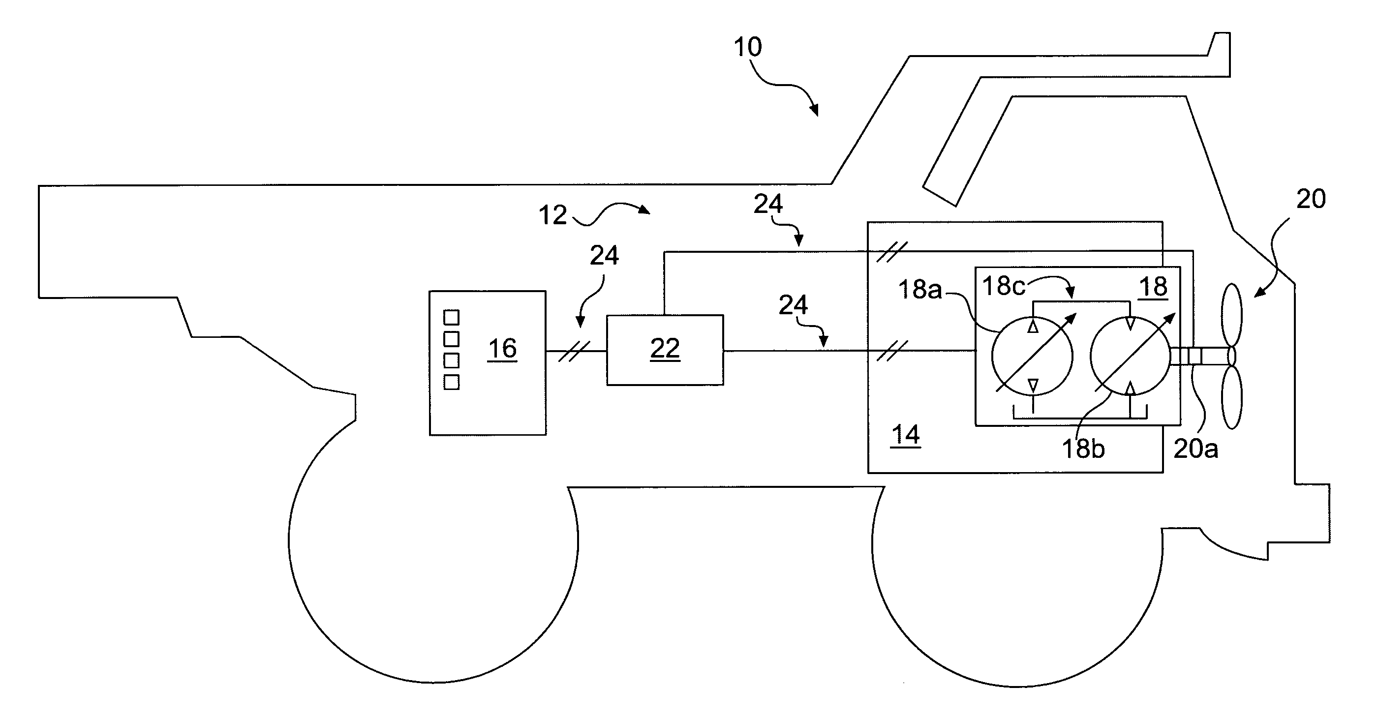
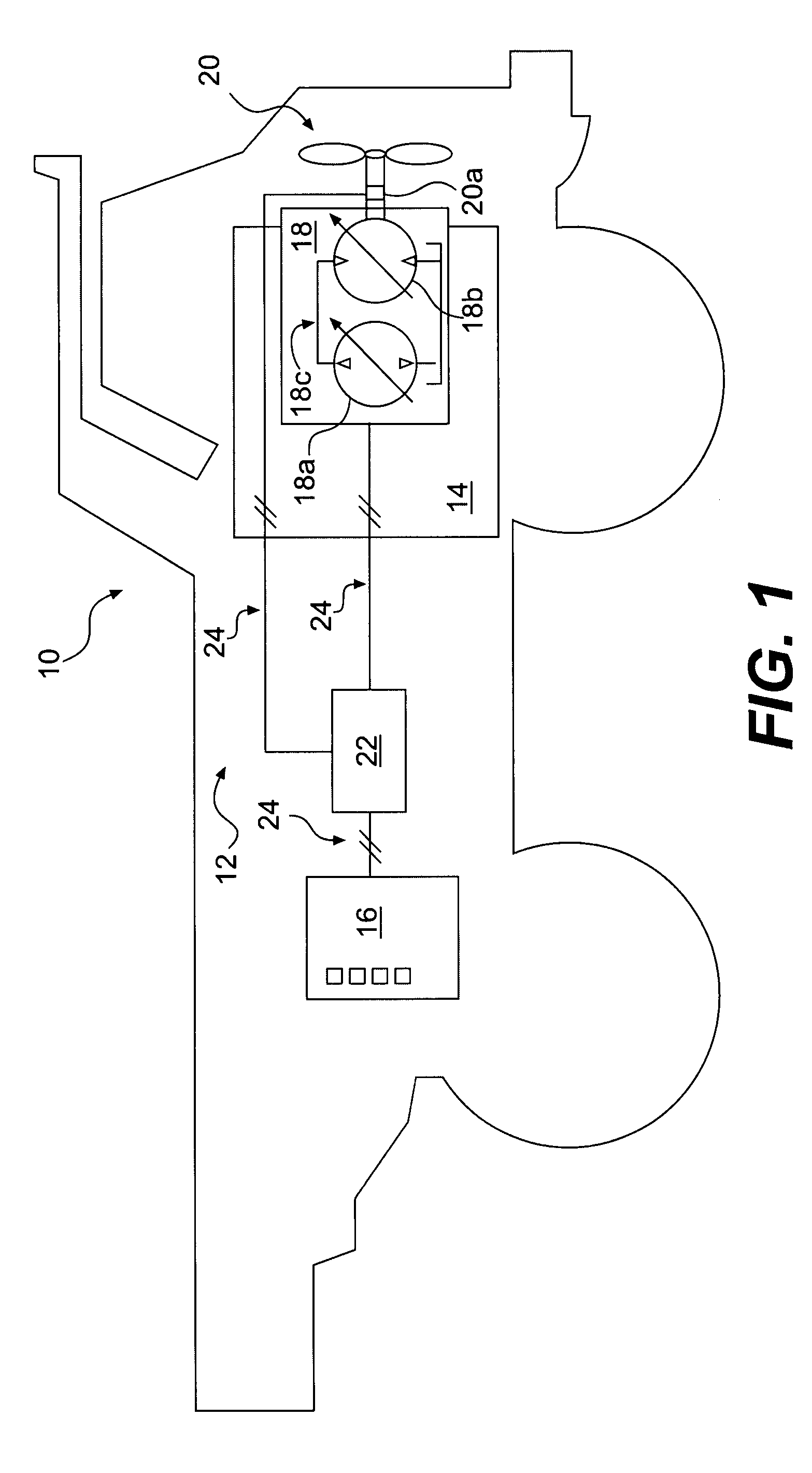
[0010]FIG. 1 illustrates a machine 10 including an exemplary fan control system 12. Machine 10 may include any mobile or stationary machine that generates heat during operation and benefits from cooling airflow. For example, machine 10 may be a passenger vehicle, an excavating machine, an aircraft, a marine vessel, a locomotive, an electrical generator or motor, or any other suitable machine. Machine 10 may include a main power source 14 to, among other things, propel and / or power other operations of machine 10. For example, power source 14 may be a diesel engine, a gasoline engine, a natural gas engine, a fuel cell, a motor, or any other suitable power source.

[0011]Fan control system 12 may be a standalone system or a subsystem of an overall machine cooling system (not shown). System 12 may include one or more sensors 16, a means 18 for driving a fan 20, and a controller 22. Controller 22 may be communicatively coupled to sensors 16, means 18 and / or any other components or systems ...


PUM


Abstract

A fan speed control system for a machine is disclosed. The control system may include a fan to provide a flow of coolant to the machine. The system may further include a first sensor configured to generate a first signal indicative of an operational parameter of the machine, a second sensor associated with the fan to generate a second signal indicative of an actual speed of the fan, and a controller communicatively coupled to the fan, the first sensor, and the second sensor. The controller may be configured to generate a third signal indicative of a desired fan speed based on the first signal, and a fourth signal indicative of a difference between the desired fan speed and the actual fan speed. The controller may drive the fan based on the third signal and the fourth signal.

Description

BACKGROUND[0001]Mobile machines, such as, for example, on- or off-highway vehicles; and stationary machines, such as engines, generators, electronic appliances, etc., typically generate a substantial amount of heat during operation. The heat, if not properly dealt with, can reduce fuel efficiency and / or cause damage to machine components. As such, machines typically include cooling systems to move the heat away from the machine during operation. The cooling systems may include, among other things, a fan configured to draw heat away from, and / or push cooling airflow toward machine components.[0002]Due to varying environmental conditions, it may be beneficial to run the fan at a variable speed. For example, an on-highway truck hauling a load up a steep incline on a hot summer day may require more cooling than the same truck idling at a stop on a cold winter day. To the extent it may be necessary and / or efficient to run the fan at a high speed under the former circumstance, it may be u...

Claims


Application Information

Patent Timeline
Patent Type & Authority Applications(United States)
IPC IPC(8): G05B23/02
CPCF01P7/044F01P2023/08
Inventor SCHURICHT, SCOTT RICHARDNORMAN, DOUGLAS I.PERESTA, PAUL W.WILSON, ARVIL DUANE
Owner CATERPILLAR INC
Why Eureka
Try Eureka