Method and apparatus for generating low rate turbo codes

a turbo code and code generation technology, applied in the field of communication systems, can solve the problems of long constraint length, the error performance of the code cannot be improved, and the complexity of the decoder design is prevented from practical, so as to achieve the effect of low code ra

Active Publication Date: 2008-10-02
HUGHES NETWORK SYST
View PDF5 Cites 31 Cited by
  • Summary
  • Abstract
  • Description
  • Claims
  • Application Information

AI Technical Summary

Problems solved by technology

Although long constraint length convolutional codes can also approach the Shannon limit, decoder design complexity prevents practical, wide spread adoption.
Code rate is an important factor that has a significant effect on the error performance of the code.
There is a continual challenge to devise codes that edge closer to the Shannon limit, while minimizing complexity.

Method used


Image

  • Method and apparatus for generating low rate turbo codes
  • Method and apparatus for generating low rate turbo codes
  • Method and apparatus for generating low rate turbo codes

Examples


Embodiment Construction

[0023]A method for generating low rate turbo codes is described. In the following description, for the purposes of explanation, numerous specific details are set forth in order to provide a thorough understanding of the invention. It is apparent, however, that the invention may be practiced without these specific details or with an equivalent arrangement. In other instances, well-known structures and devices are shown in block diagram form in order to avoid unnecessarily obscuring the invention.

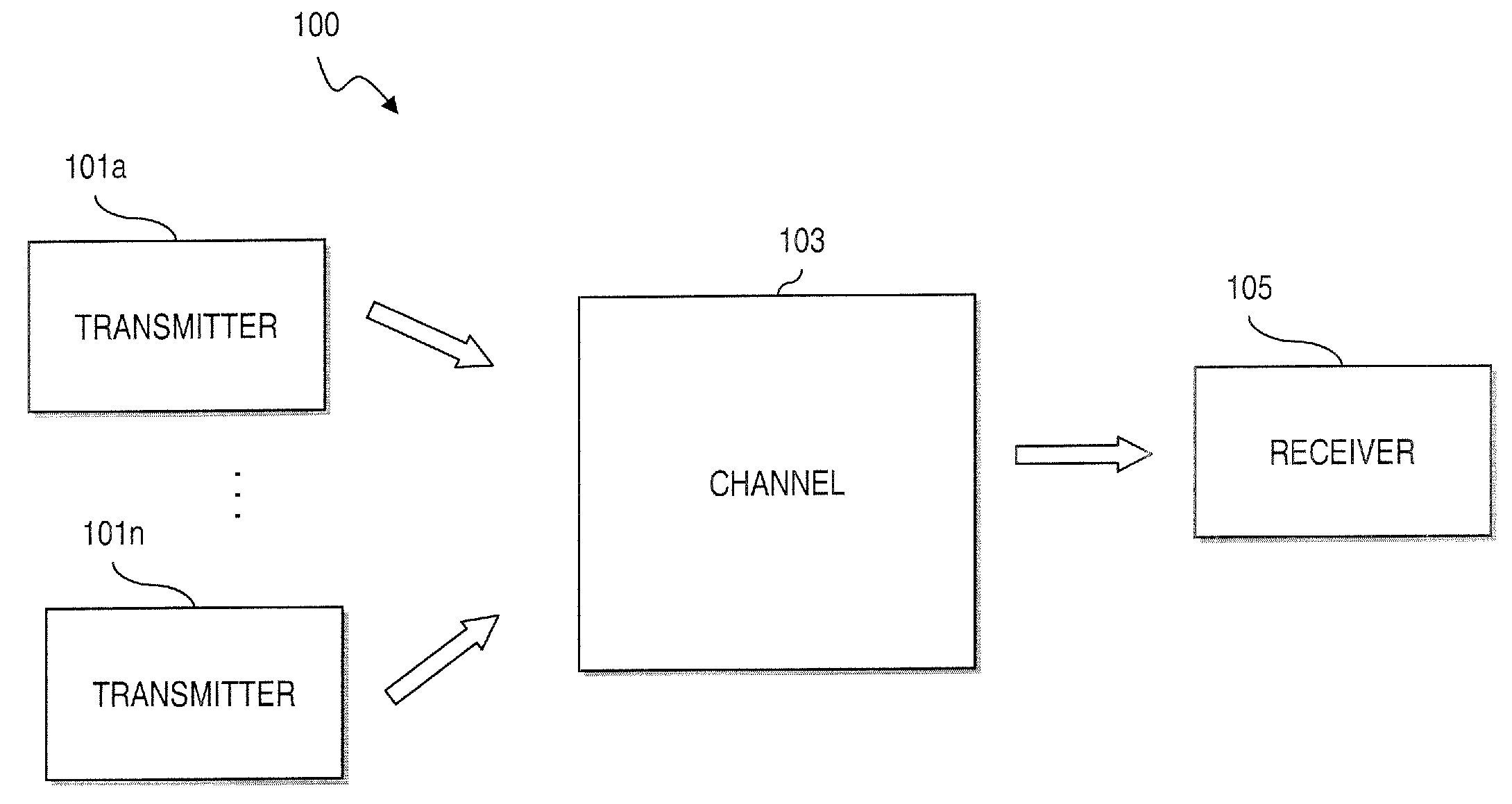
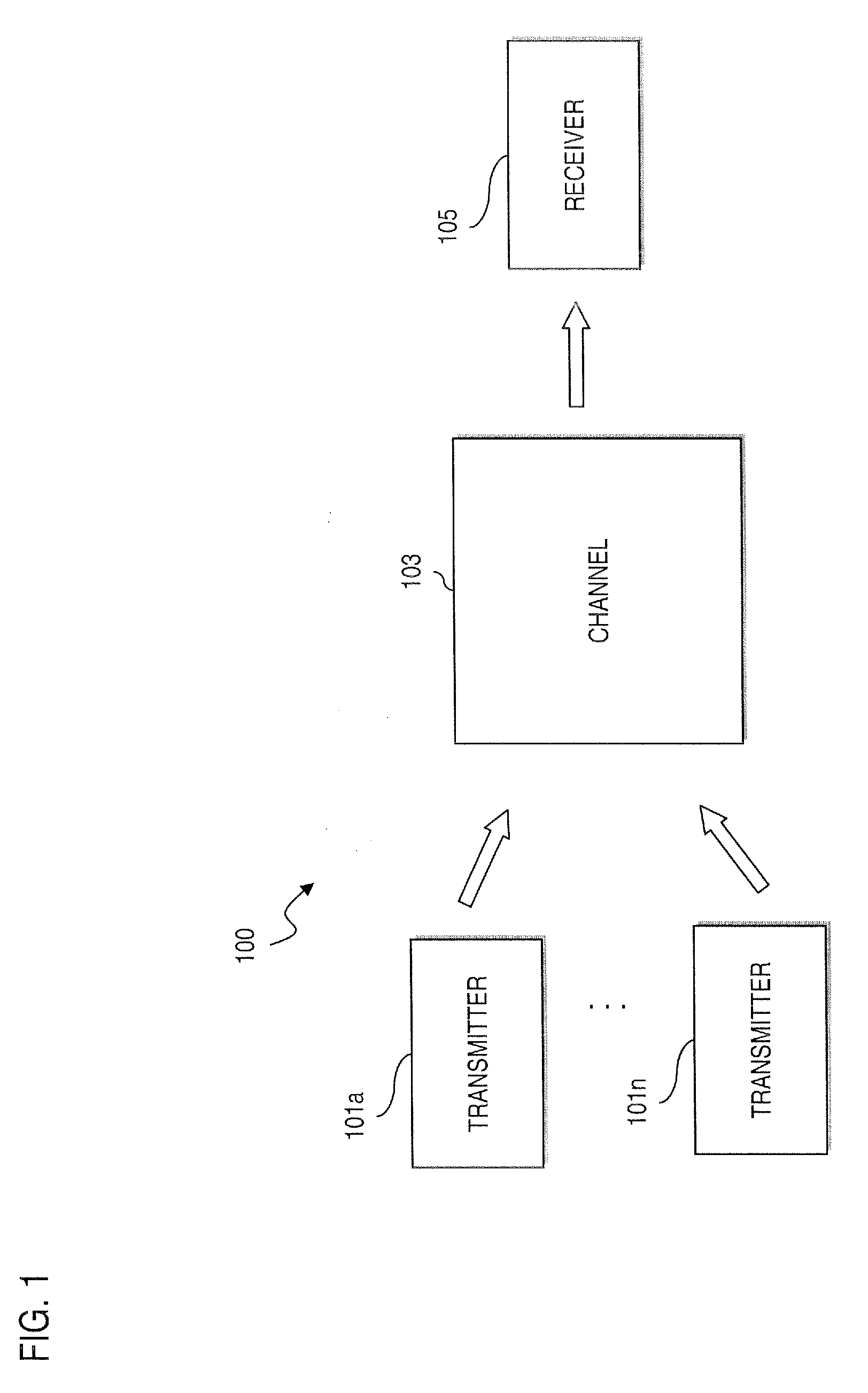
[0024]FIG. 1 is a diagram of a communications system configured to utilize low rate turbo codes, according to various exemplary embodiments. A digital communications system 100 includes one or more transmitters 101 that generate signal waveforms across a communication channel 103 to one or more receivers 105 (of which one is shown). In this discrete communications system 100, the transmitter 101 has a message source that produces a discrete set of possible messages; each of the possible messa...


PUM


Abstract

An approach is provided for encoding information bits to output a coded signal using turbo code encoding with a low code rate.

Description

RELATED APPLICATIONS[0001]This application is related to, and claims the benefit of the earlier filing date under 35 U.S.C. § 119(e) of, U.S. Provisional Patent Application (Ser. No. 60 / 908,340) filed Mar. 27, 2007 (Attorney Docket: 115426-1147), entitled “Efficient USAT Transmission Using Low-Rate Turbo Codes and Scrambled Coded Multiple Access (SCMA) Techniques”; the entirety of which is incorporated herein by reference.FIELD OF THE INVENTION[0002]The present invention relates to communication systems, and more particularly to coded systems.BACKGROUND OF TUE INVENTION[0003]Nearly all communication system relies on some form of error control for managing errors that may occur due to noise and other factors during transmission of information through a communication channel. These communications systems can include satellite systems, fiber-optic systems, cellular systems, and radio and television broadcasting systems. Efficient error control schemes implemented at the transmitting en...

Claims


Application Information

Patent Timeline
Patent Type & Authority Applications(United States)
IPC IPC(8): H03M7/00
CPCH03M13/2903H03M13/2957
Inventor EROZ, MUSTAFALEE, LIN-NAN
Owner HUGHES NETWORK SYST
Why Eureka
Try Eureka