Visual inspection apparatus

a technology of visual inspection and apparatus, which is applied in the field of visual inspection apparatus, can solve problems such as inability to obtain an image, work cracks, and work prone to internal stress

Inactive Publication Date: 2008-10-02
OLYMPUS CORP
View PDF6 Cites 15 Cited by
  • Summary
  • Abstract
  • Description
  • Claims
  • Application Information

AI Technical Summary

Problems solved by technology

When forming a pattern, such as a circuit, in a work, such as a semiconductor wafer, warpage or internal stress may occur in the work due to heat treatment.
The work may crack while a circuit is being manufactured if the warpage or the internal stress of the work increases.
However, in the known apparatus configuration, it was not possible to obtain an image if the imaging camera was not provided in a bright field range.
Since it is difficult to illuminate a work brightly in a wide range in the known illumination portion, observing in the bright field cannot be satisfactorily performed if the imaging camera is moved.
However, it was not possible to perform observing in the dark field in the known apparatus configuration.

Method used


Image

  • Visual inspection apparatus
  • Visual inspection apparatus
  • Visual inspection apparatus

Examples


Embodiment Construction

[0035]Hereinafter, a preferred embodiment for executing the invention will be described in detail with reference to the accompanying drawings. However, it is needless to say that the invention is not limited to the embodiment.

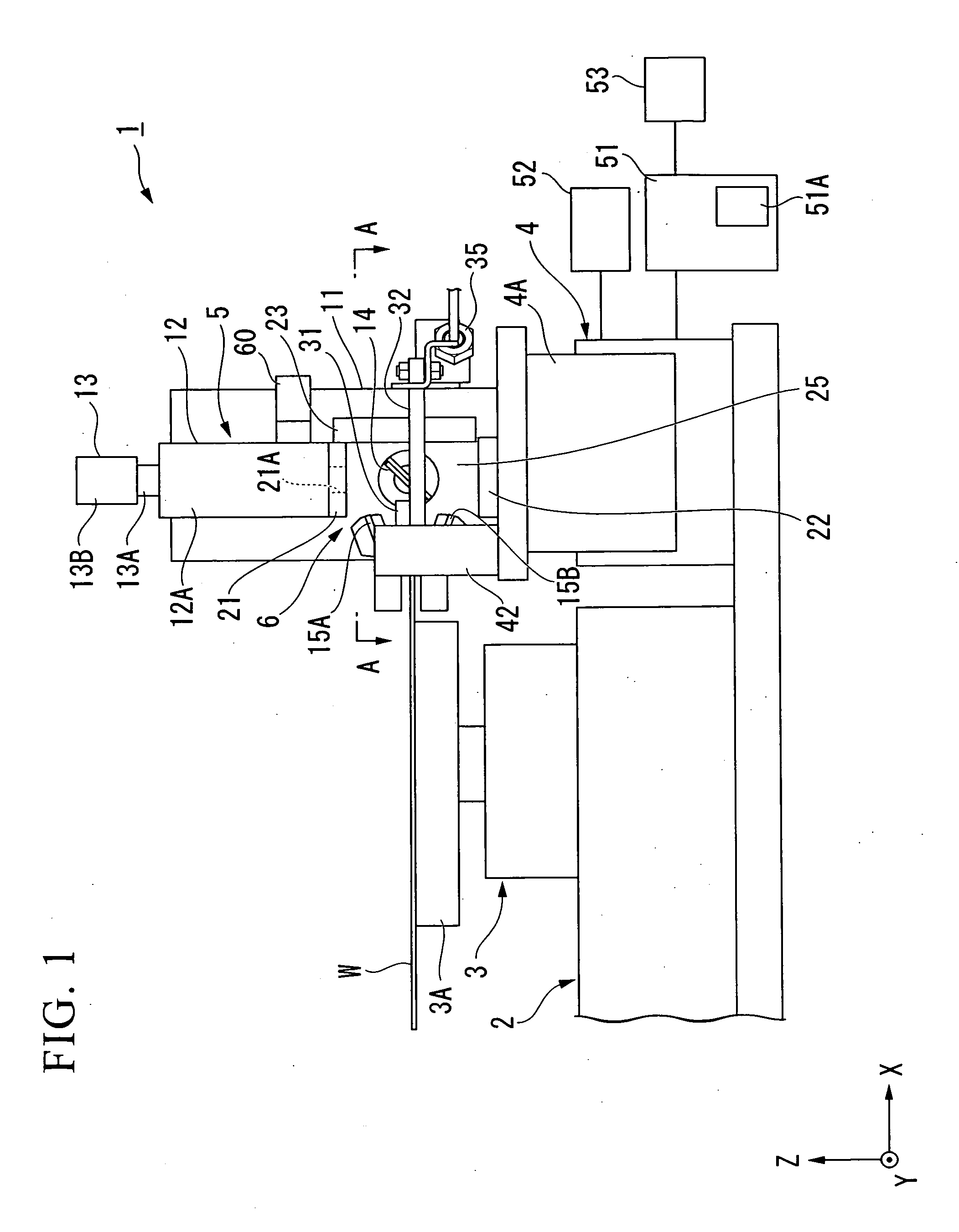
[0036]As shown in FIG. 1, a visual inspection apparatus 1 is provided with an XYθ stage 3 for absorbing and holding a wafer W, which is a work, on a base 2, and a Z stage 4.

[0037]The XYθ stage 3 has a support portion 3A that supports the wafer W, and an absorbing portion (not shown) that absorbs and holds a middle part of a bottom surface of the wafer W is provided in the support portion 3A. The XYθ stage 3 is configured to be able to move the support portion 3A in two directions (X direction and Y direction) perpendicular to each other in the horizontal direction and to rotate the support portion 3A in a Z-axis direction perpendicular to the X and Y directions. Driving of the XYθ stage 3 is controlled by a motor (not shown). As the motor, a motor that can perf...


PUM

PropertyMeasurementUnit
inclination angleaaaaaaaaaa
angleaaaaaaaaaa

Abstract

A visual inspection apparatus includes an upper illuminator, a lower illuminator, a side illuminator, and a pair of inclined illuminators, which illuminate the peripheral edge of a wafer, and illuminates the peripheral edge of the wafer brightly. A gap is formed in the upper illuminator and illumination light of an epi-illumination portion is injected through the gap. The illumination light of the epi-illumination portion is refracted and reflected by a first mirror to illuminate the peripheral edge of the wafer. The illumination position is changed by moving second mirrors together as needed. An image of the peripheral edge is acquired in an imaging portion disposed at the same axis as the epi-illumination portion.

Description

BACKGROUND OF THE INVENTION[0001]1. Field of the Invention[0002]The present invention relates to a visual inspection apparatus that performs visual inspection of a peripheral edge of a work, such as a wafer. Priority is claimed on Japanese Patent Application No. 2007-80546, filed Mar. 27, 2007, the content of which is incorporated herein by reference.[0003]2. Description of Related Art[0004]When forming a pattern, such as a circuit, in a work, such as a semiconductor wafer, warpage or internal stress may occur in the work due to heat treatment. The work may crack while a circuit is being manufactured if the warpage or the internal stress of the work increases. Therefore, a technique of detecting the existence of a crack for which cracking may progress in the future by observing the peripheral edge of the work beforehand is known.[0005]An apparatus for observing the peripheral edge of a work includes an apparatus in which a C-shaped illumination portion is provided adjacent to the pe...

Claims


Application Information

Patent Timeline
Patent Type & Authority Applications(United States)
IPC IPC(8): G01N21/88
CPCG01N21/9503G01N21/8806
Inventor YOKOTA, ATSUTOSHIKURATA, SHUNSUKE
Owner OLYMPUS CORP
Why Eureka
Try Eureka