Image reading apparatus and control method thereof

a reading apparatus and image technology, applied in the direction of electrical equipment, pictoral communication, etc., can solve the problems of front end of original catches on elastic members, streaks will occur on read images read by image sensors, and continue to occur, so as to reduce the number of streaks

Active Publication Date: 2008-10-02
CANON DENSHI KK
View PDF7 Cites 21 Cited by
  • Summary
  • Abstract
  • Description
  • Claims
  • Application Information

AI Technical Summary

Benefits of technology

[0023]The present invention provides an image reading apparatus and a control method thereof capable of continually conveying a plurality of originals in a stable manner while cleaning a contact glass of an image sensor and reducing streaks occurring in read images.

Problems solved by technology

Therefore, when the platen roller continues to rotate during the conveying of an original, there are cases where the front end of the original catches on the elastic member.
In addition, there may be cases where the elastic member is inadvertently captured in a read image or where variations in density or defocusing occurs due to rippling caused when the elastic member presses a part of the original against a contact glass of the image sensor.
However, if contaminants such as paper dust adhere to the contact glass during continuous conveying of a plurality of originals, streaks will occur on the read image read by the image sensor.
In addition, if the contaminants remain adhered, streaks will continue to occur even in read images read after the aforementioned original.
Therefore, cleaning of deposition of stains adhering on the cleaning member 316 requires disassembling the mechanism around the platen roller 310 and cleaning the cleaning member 316 after removing the platen roller 310 from the apparatus main body, raising a problem in that cleanup work of the cleaning member 316 requires a significant amount of effort.
Furthermore, with the conventional image reading apparatus described above, in the case where a skew of the original 308 occurs, a corner of the original 308 is delayed by the skew, whereby cleaning performed at predetermined timing may cause damages to the original 308 or jamming.

Method used


Image

  • Image reading apparatus and control method thereof
  • Image reading apparatus and control method thereof
  • Image reading apparatus and control method thereof

Examples


first embodiment

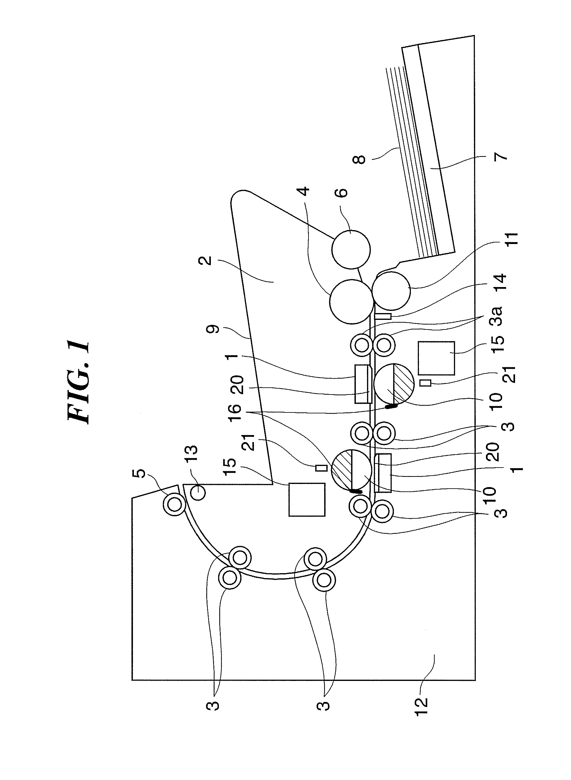
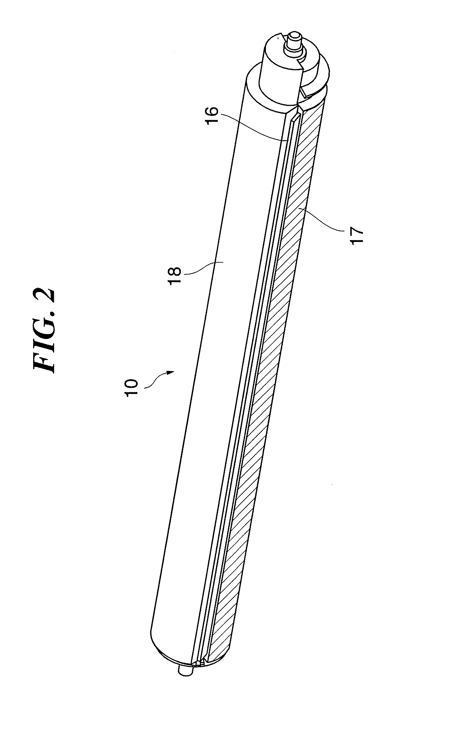
[0072]FIG. 1 is a cross-sectional diagram schematically showing a configuration of an image reading apparatus according to the present invention, and FIG. 2 is a perspective view for explaining a platen roller shown in FIG. 1.

[0073]With this image reading apparatus, as shown in FIG. 1, when an original mounting table 7 on which originals 8 are placed is elevated and an original 8 contacts a pickup roller 6, the original 8 picked up by the pickup roller 6 is fed by a feeding roller 4.

[0074]When two or more originals 8 are picked up at the same time by the pickup roller 6, the originals 8 are separated into individual sheets by a retard roller 11 and then fed. An image on the fed original 8 is read by an image sensor 1 and the read image data is transferred to an image processing section, not shown. The front end and the rear end of the fed original 8 are detected by a registration sensor 14. Conveying timing and the like are controlled by controlling the rotation and stopping of a re...

third embodiment

[0140]FIG. 10 is a cross-sectional diagram schematically showing a configuration of an image reading apparatus according to the present invention. Since the basic configuration of the image reading apparatus according to the present embodiment is approximately the same as the conventional image reading apparatus already described with reference to FIG. 30, portions overlapping with or corresponding to the image reading apparatus shown in FIG. 30 will be assigned like reference characters and a description thereof will either be omitted or simplified.

[0141]As shown in FIG. 10, in the image reading apparatus according to the present embodiment, skew detection sensors 140 and 141 are disposed upstream of the registration sensor 314, and a platen roller 125 is used instead of the conventional platen roller 310.

[0142]Describing now the platen roller 125 with reference to FIG. 12, the platen roller 125 includes a half-cylindrical black member 126, a half-cylindrical white member 127 and a...

fifth embodiment

[0189]With the present fifth embodiment, a cleaning mode setting screen such as that shown in FIG. 19 is displayed on an operation display portion of the image reading apparatus or a display portion of an external control apparatus (a PC or the like) connected to the image reading apparatus.

[0190]In the setting screen shown in FIG. 19, when “cleaning is performed if skew is detected” (hereinafter referred to as the “cleaning priority mode”) is selected, the control circuit 900 performs the control of the third embodiment described above to alter timings according to the skew amount and performs cleaning, and when “cleaning is not performed if skew amount is large” (hereinafter referred to as the “speed priority mode”) is selected, the control circuit 900 performs the control of the fourth embodiment described above. The speed priority mode may alternatively be arranged so that “cleaning is not performed when a skew is detected”. As shown, with the present embodiment, since a cleanin...


PUM


Abstract

An image reading apparatus capable of continually conveying a plurality of originals in a stable manner while cleaning a contact glass of an image sensor and reducing streaks occurring in read images. An image sensor reads an original image via a contact member which the conveyed original may contact. A cleaning member, being provided on a turning member which is able to rotate or swing and disposed at a position opposing the image sensor, cleans the contact member's surface which the original may contact. The turning member is turned by a driving unit. A controlling unit controls the driving unit to turn the turning member so that cleaning of the contact member is performed by the cleaning member after the original has passed an image reading position of the image sensor and before a subsequent original reaches the image reading position.

Description

BACKGROUND OF THE INVENTION[0001]1. Field of the Invention[0002]The present invention relates to an image reading apparatus such as a scanner which reads an image on an original conveyed using a conveying mechanism such as a roller, and a control method of the image reading apparatus.[0003]2. Description of the Related Art[0004]An example of a conventional image reading apparatus is shown in FIG. 30.[0005]The image reading apparatus shown in FIG. 30 includes a lower unit 301 and an upper unit 302 supported so as to be vertically turnable via a hinge 313 with respect to the lower unit 301. A turning movement of the upper unit 302 causes an original conveying section to open and / or close. An opened state and / or a closed state of the original conveying section is detected by an opening-closing detection sensor 337. A convey path is formed when the original conveying section assumes a closed state to enable conveying of an original.[0006]The image reading apparatus starts an image readi...

Claims


Application Information

Patent Timeline
Patent Type & Authority Applications(United States)
IPC IPC(8): H04N1/04
CPCH04N1/00909H04N1/1215H04N1/125H04N1/193H04N1/2032H04N2201/0081
Inventor KATO, SHINOBUOKITSU, KATSUHIKOHIGUCHI, HIROKAZU
Owner CANON DENSHI KK
Why Eureka
Try Eureka