Arrangement For Optimizing the Frequency Response of an Electro-Acoustic Transducer

a technology of electro-acoustic transducers and frequency response, which is applied in the direction of electrical transducers, transducer details, semiconductor devices, etc., can solve the problems of inability to apply existing electro-acoustic transducers, inability to reduce the influence of modes on the frequency response of electro-acoustic transducers, and inability to achieve the effect of reducing the influence of modes

Inactive Publication Date: 2008-10-02
KNOWLES ELECTRONICS ASIA
View PDF19 Cites 11 Cited by
  • Summary
  • Abstract
  • Description
  • Claims
  • Application Information

AI Technical Summary

Benefits of technology

[0006]It is an object of the invention to provide an arrangement of the type defined in the opening paragraph, a loudspeaker and a microphone of the type defined in the second paragraph, and a loudspeaker cabinet of the type defined in the third paragraph, in which the disadvantage defined above is avoided.
[0010]The characteristic features according to the invention provide the advantage that the influence of characteristic inherent vibrations or eigenvibrations, i.e. the modes of the membrane of the electro-acoustic transducer, on the frequency response may be efficiently reduced by the damping element or, more precisely said, by acoustically coupling the membrane and the damping element as rigidly as possible in order to reduce characteristic inherent vibrations or eigenvibrations. The word “rigid” and the term “rigid acoustic coupling” as well as the expression “intimate acoustic coupling” used in this patent, all mean that essentially the complete air masses moved by the membrane flow through the damping element and merely minor air streams bypass the damping element. It should be emphasized that “rigid acoustic coupling” does not mean a mechanical coupling of the damping element and the membrane, as known from U.S. Pat. No. 4,276,452. In particular, the frequency response of the electro-acoustic transducer can be improved in that it better approaches a flat frequency response with no significant anomalies through the measures according to the invention. This can make the sound reproduction of the transducer more authentic than without the measures of the invention. The damping element according to the invention causes damping of the air moved between the damping element and the membrane of the transducer by the membrane displacements. Thus, the damping element causes conversion of the kinetic energy of the air flow or the sound energy into thermal energy and, therefore, absorption of sound generated by the membrane of the electro-acoustic transducer. The air damping may decrease the Q (quality factor) of one or more anomalies in the frequency response. According to the invention, not only characteristic vibrations in the lower acoustic frequency range are reduced, but also characteristic vibrations in the higher acoustic frequency range may be efficiently reduced. The invention may be applied to any electro-acoustic transducer such as a speaker or a microphone, or to a loudspeaker cabinet, comprising one or more speakers. Furthermore, the invention may be applied to electro-acoustic transducers with plane-plate, cone- or dome-shaped membranes. In contrast to the transducer disclosed in U.S. Pat. No. 4,276,452, the invention is a simpler construction which requires no reconstruction of a transducer and may be applied to existing transducers.
[0012]A further reduction in the influence of modes may be achieved if the damping element has dimensions such that its area facing the membrane is at least as large as the area of the membrane. This measure avoids air moved by the displacement of the membrane bypassing the damping element.
[0021]Furthermore, it is preferred that the damping element is shaped like a plate. A plate may be produced easily and can be applied to different membrane shapes. A damping plate may be most suitable for an electro-acoustic transducer with a plane membrane since the air gap between the damping plate and the membrane may be accurately adjusted.
[0023]According to a further embodiment of the invention, the damping element may comprise several layers of damping material arranged one behind the other. Thus, the sound absorbing effects of different materials may be combined in order to achieve a highly efficient sound absorption.

Problems solved by technology

In particular, such modes cause undesired anomalies (peaks, dips and points of inversion) in the frequency response.
One disadvantage of the disclosed absorbing method is that it cannot be applied to existing electro-acoustic transducers since it requires a reconstruction of an electro-acoustic transducer, particularly of its membrane.
Thus, this is an expensive method of reducing the influence of modes on the frequency response of an electro-acoustic transducer.

Method used


Image

  • Arrangement For Optimizing the Frequency Response of an Electro-Acoustic Transducer
  • Arrangement For Optimizing the Frequency Response of an Electro-Acoustic Transducer
  • Arrangement For Optimizing the Frequency Response of an Electro-Acoustic Transducer

Examples


Embodiment Construction

[0030]Identical, similar, and functionally identical or similar elements can be denoted with the same reference numerals in the following description.

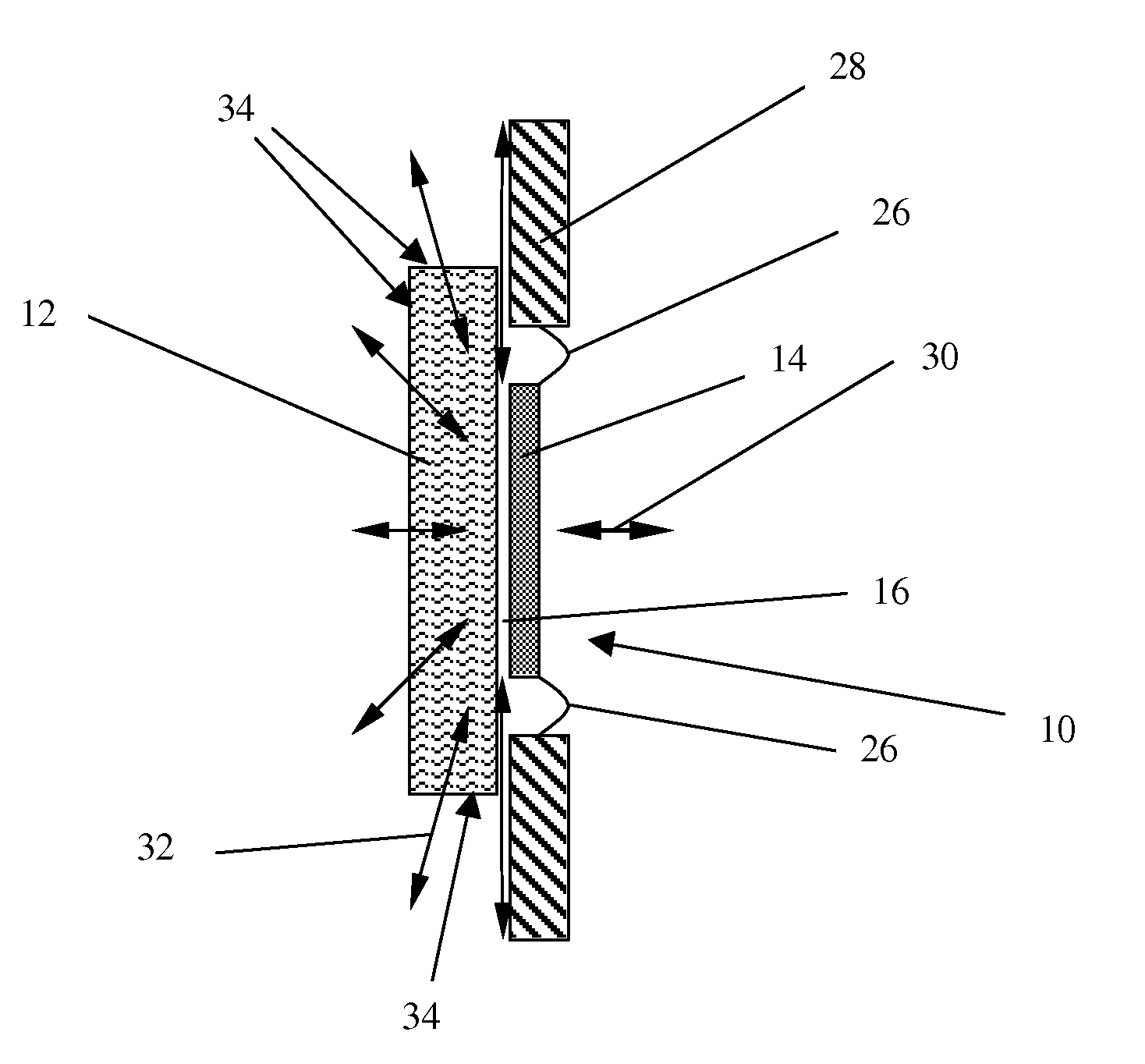
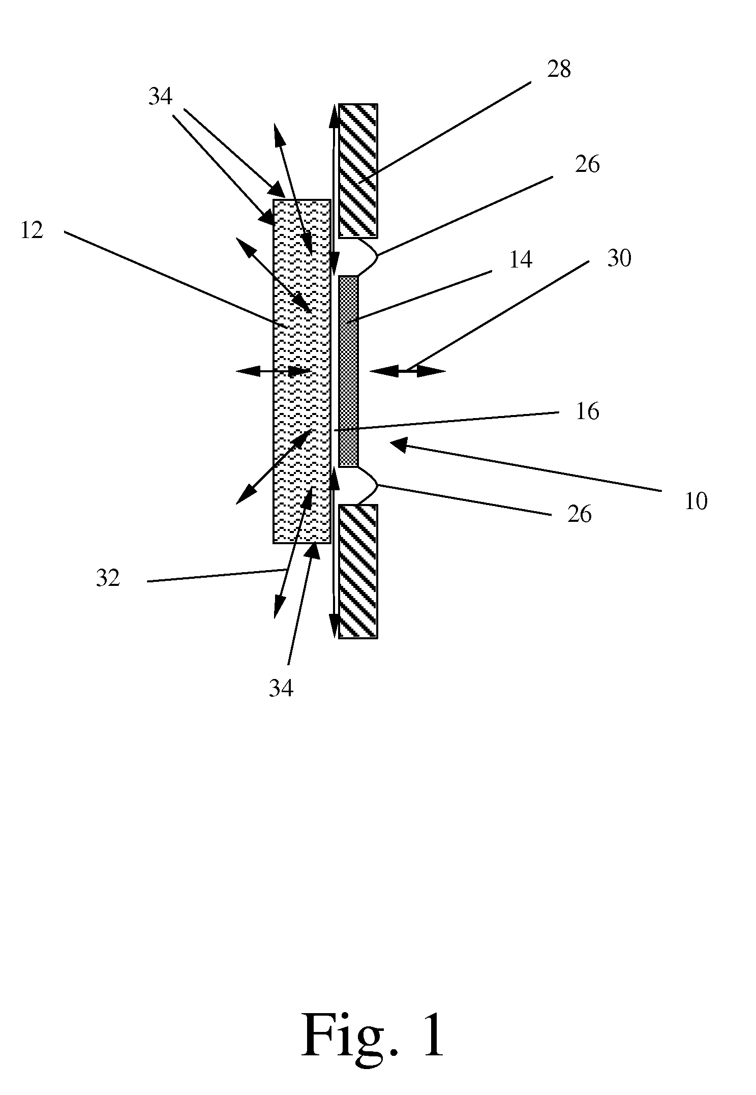
[0031]FIG. 1 shows an electro-acoustic transducer configured as a loudspeaker 10 with a plane membrane 14, for example a rigid plate, which is mounted in an opening of an acoustically “open” housing 28, for example a wall with an opening for the loudspeaker 10. The membrane 14 of the loudspeaker 10 is mounted at the housing 28 by a suspension 26, which is flexible such that the membrane 14 may oscillate or vibrate unimpeded.

[0032]A plate-shaped damping element 12 comprising a porous material is rigidly mounted immediately behind the sound emanating side of the membrane 14 such that only a small air gap 16 is provided between the membrane 14 and the damping element 12. The air gap 16 is sized so small that the membrane 14 is acoustically coupled to the damping element 12 as rigidly as possible without touching it, in order to optimally ...


PUM


Abstract

An arrangement for optimizing the frequency response of an electro-acoustic transducer (10), comprising the electro-acoustic transducer (10) and a damping element (12) arranged behind the sound emanating or receiving side of a membrane (14) of the electro-acoustic transducer (10), wherein an air gap (16) is provided between the damping element (12, 13) and the membrane (14), which air gap (16) is sufficiently small for intimately acoustically coupling the membrane (14) with the damping element (12, 13), wherein the damping element (12, 13) is adapted to dampen an air flow created by the membrane (14) when moving.

Description

FIELD OF THE INVENTION[0001]The invention relates to an arrangement for optimizing the frequency response of an electro-acoustic transducer.[0002]The invention further relates to a loudspeaker or microphone.[0003]The invention finally relates to a loudspeaker cabinet, especially the housing of small multi-media devices, e.g. mobile (i.e. cell) phones.BACKGROUND OF THE INVENTION[0004]Membranes of electro-acoustic transducers such as loudspeakers or microphones have one or more characteristic inherent vibrations or eigenvibrations, also called “modes”, which influence the transducer frequency response. In particular, such modes cause undesired anomalies (peaks, dips and points of inversion) in the frequency response. However, a flat frequency response is desired in order to achieve an authentic sound reproduction. Especially, flat membranes, being formed from more or less rigid plates, are sensitive to modes, but also other membranes, such as cone-shaped membranes, as well as soft non...

Claims


Application Information

Patent Timeline
Patent Type & Authority Applications(United States)
IPC IPC(8): H04R1/20
CPCH04R1/2807H04R1/2811H04R2499/11H01L2224/48091H01L2924/00014H01L2924/3011H01L2924/00
Inventor HADDAD, GHOLAMALIRUBERL, ERNSTPOLDY, CARL
Owner KNOWLES ELECTRONICS ASIA
Why Eureka
Try Eureka