Driving mechanism
a technology of driving mechanism and motor shaft, which is applied in the direction of generator/motor, television system, instruments, etc., can solve the problems of not being able to achieve a further increase in speed, not necessarily satisfactory, and conventional structures
- Summary
- Abstract
- Description
- Claims
- Application Information
AI Technical Summary
Benefits of technology
Problems solved by technology
Method used
Image
Examples
first embodiment
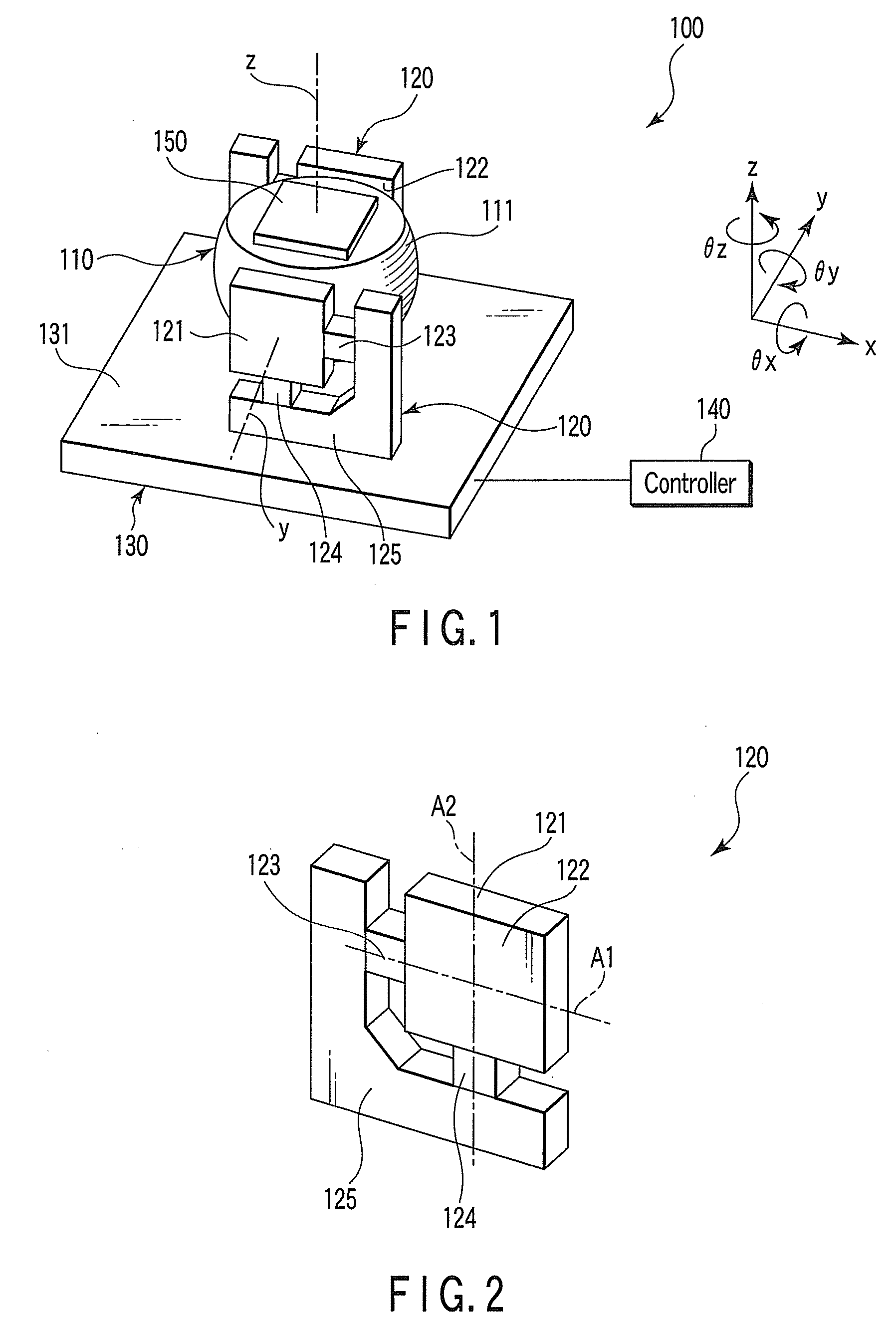
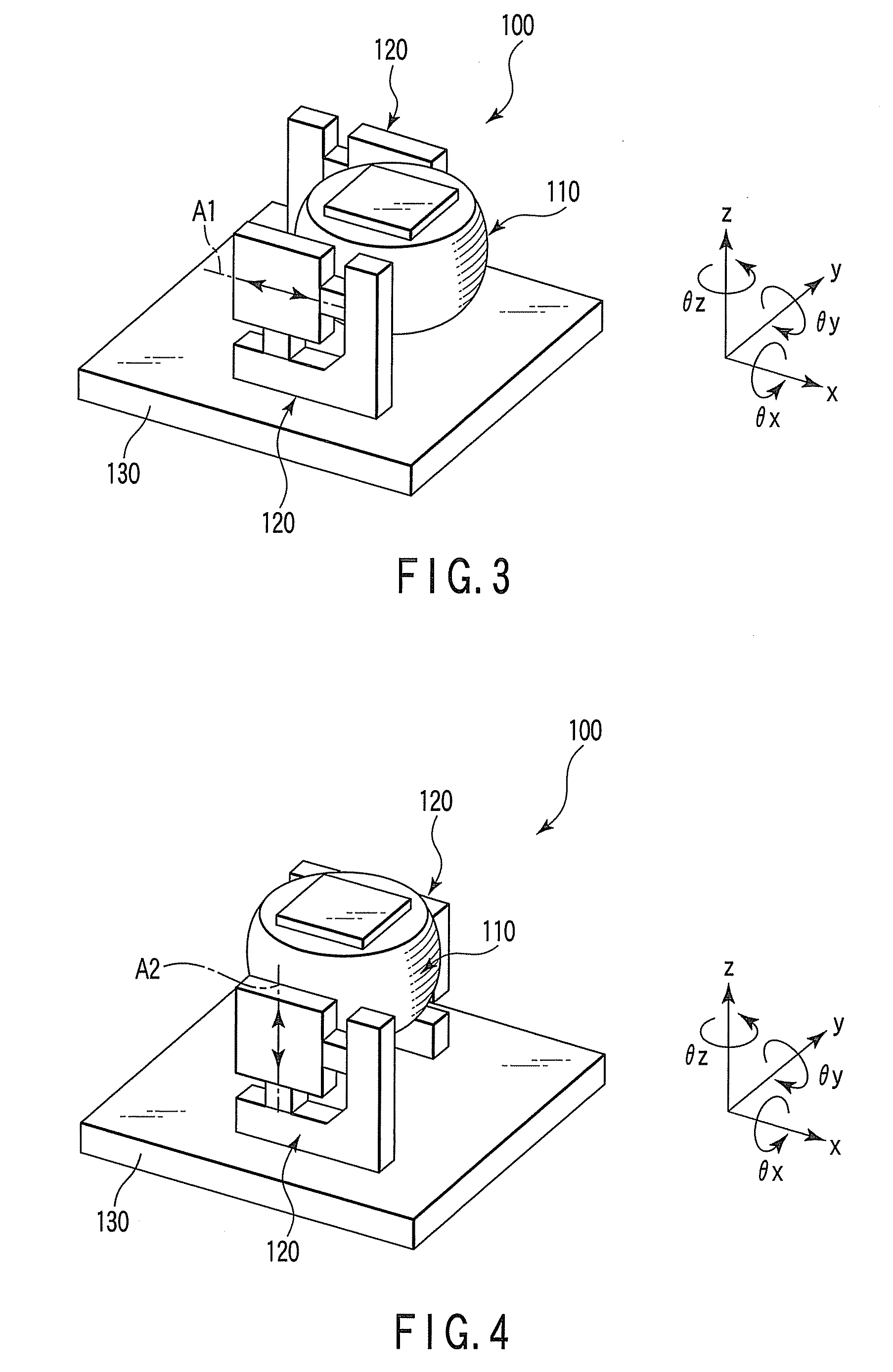
[0039]The arrangement of a driving mechanism according to this embodiment will be described with reference to FIGS. 1 and 2.
[0040]As shown in FIG. 1, a driving mechanism 100 of this embodiment includes a driven member 110 partially having a spherical surface 111, two piezoelectric units 120 that support the driving mechanism 100 between them and drive it, a base 130 that holds the piezoelectric units 120, and a controller 140 that controls the piezoelectric units 120.
[0041]As shown in FIG. 2, each of the piezoelectric units 120 includes a driving portion 121 having a flat surface 122 in contact with the spherical surface 111 of the driven member 110, a first piezoelectric element 123 that linearly moves the driving portion 121 along a first axis A1 parallel to the flat surface 122, a second piezoelectric element 124 that linearly moves the driving portion 121 along a second axis A2 parallel to the flat surface 122 and perpendicular to the axis A1, and a support member 125 that suppo...
second embodiment
[0051]The second embodiment will be described with reference to FIG. 7. The same reference numerals as in FIG. 7 denote the same members in the first embodiment, and a detailed description thereof will be omitted.
[0052]As shown in FIG. 7, a driving mechanism 200 of this embodiment includes a driven member 110 partially having a spherical surface 111, three piezoelectric units 120 that support the driven member 110 between them and drive the driven member 110, a base 230 that holds the piezoelectric units 120, and a controller 240 that controls the piezoelectric units. The three piezoelectric units 120 are arranged so that driving portions 121 are arranged at equal intervals to surround the driven member 110. Support members 125 are fixed on the base 230 so that the driving portions 121 are located on a circumference slightly smaller than the great circle of the spherical surface of the driven member 110. The great circle is a circle on the cut surface obtained by cutting the spheric...
third embodiment
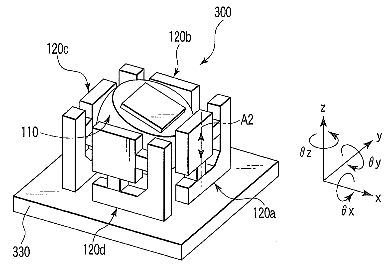
[0059]The arrangement of a driving mechanism according to the third embodiment will be described with reference to FIG. 8. The same reference numerals as in FIG. 8 denote the same members in the first embodiment, and a detailed description thereof will be omitted.
[0060]As shown in FIG. 8, a driving mechanism 300 according to this embodiment includes a driven member 110 partially having a spherical surface 111, four piezoelectric units 120 that support the driven member 110 between them and drive the driven member 110, a base 330 that holds the four piezoelectric units 120, and a controller 340 that controls the piezoelectric units.
[0061]In the following description, the four piezoelectric units are discriminated by assigning them with reference numerals 120a, 120b, 120c, and 120d. In addition, an xyz orthogonal coordinate system and the θx-, θy-, and θz-axes are set in the same manner as in the first embodiment. That is, the xyz orthogonal coordinate system is set so that the x- and...
PUM
 Abstract
Description
Claims
Application Information
 - R&D
- Intellectual Property
- Life Sciences
- Materials
- Tech Scout
- Unparalleled Data Quality
- Higher Quality Content
- 60% Fewer Hallucinations
Browse by: Latest US Patents, China's latest patents, Technical Efficacy Thesaurus, Application Domain, Technology Topic, Popular Technical Reports.
© 2025 PatSnap. All rights reserved.Legal|Privacy policy|Modern Slavery Act Transparency Statement|Sitemap|About US| Contact US: help@patsnap.com


