Electric shaker conveyor assembly

Active Publication Date: 2008-10-09
MAGNETIC PRODS
View PDF50 Cites 3 Cited by
  • Summary
  • Abstract
  • Description
  • Claims
  • Application Information

AI Technical Summary

Benefits of technology

[0012]Thus, the present invention provides a cost-effective electric shaker conveyor that converts rotary motion of the drive engine into repeated, rectilinear motion to the conveyor using an elegantly simple, effective mechanical actuation. The shaker conveyor of the present invention is relatively quiet and maintenance free. It has a lightwei

Problems solved by technology

However, belted conveyors suffer from the disadvantage that the belts are often cut by the sharp edges of the metal parts formed in stamping operations.
Frequent belt replacement increases the maintenance costs of the stamping operation.
Further, stamped parts and other debris may pass through the damaged belts and jam or foul the inner workings of the conveyor drive system.
While these types of drive mechanisms provide satisfactory reciprocal motion, they typically require a number of

Method used


Image

  • Electric shaker conveyor assembly
  • Electric shaker conveyor assembly
  • Electric shaker conveyor assembly

Examples


Example

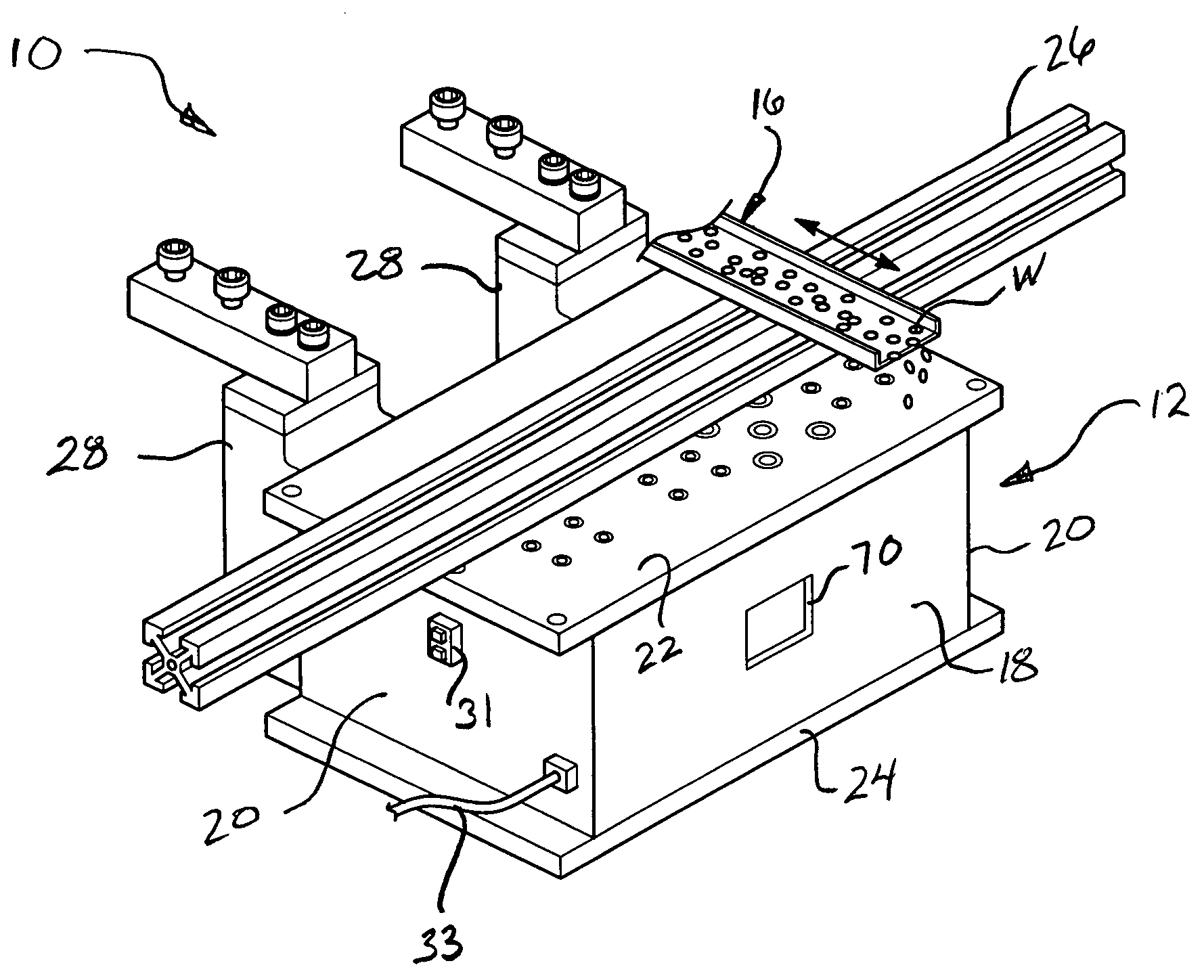
[0019]One embodiment of the shaker conveyor assembly of the present invention is generally indicated at 10 in FIGS. 1 through 5, where like numerals are used to designate like structure throughout the drawings. The shaker conveyor assembly 10 may be employed in any number of applications and neither the preceding discussion nor the description of the invention that follows should be interpreted as limiting the use of the invention.

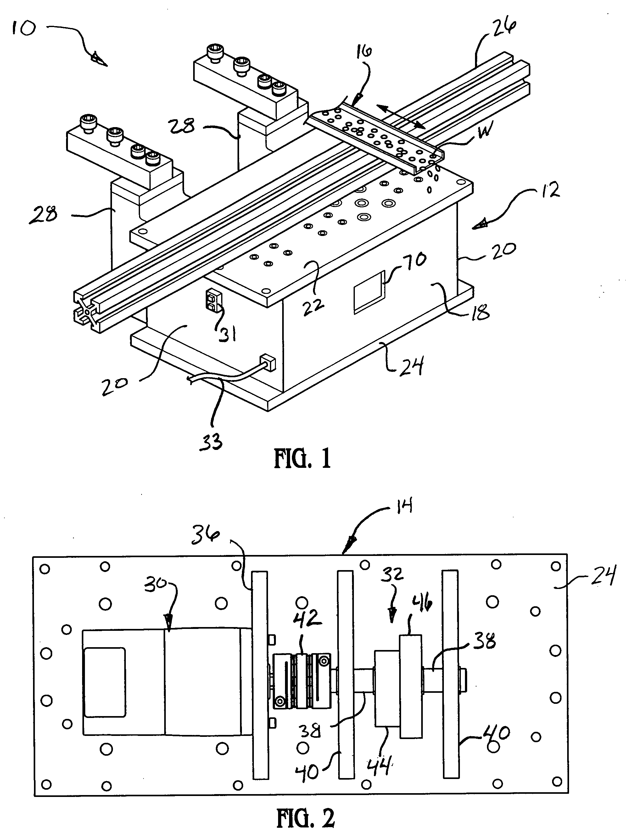
[0020]Referring now to FIGS. 1 and 2, the conveyor assembly 10 of the present invention includes a housing, generally indicated at 12, and a drive system, generally indicated at 14, supported by the housing 12 (FIG. 2). At least one transport tray is generally indicated at 16. The transport tray 16 is supported by the housing 12 and is operatively connected to the drive system 14 as will be described in greater detail below. More specifically, the housing 12 may include a plurality of walls 18, 20 and a top plate 22. The housing 12 may further include a ba...


PUM


Abstract

A shaker conveyor assembly including a housing, a drive system supported by the housing and at least one transport tray supported by the housing and operatively connected to the drive system. The drive system includes an electric motor that produces a rotary output. A cam assembly is operatively connected in driven relationship to the rotary output of the electric motor so as to rotate therewith. A cam follower assembly is operatively connected to the transport tray and is responsive to the rotation of the cam assembly to produce repeated, reciprocating, linear motion and to transmit this motion to the transport tray so as to convey items therealong.

Description

BACKGROUND OF THE INVENTION[0001]1. Field of the Invention[0002]The present invention is directed toward beltless conveyors and, more specifically, to an electric shaker conveyor assembly.[0003]2. Description of the Related Art[0004]Conveyors are well known material handling devices that have application in a wide variety of environments for transporting objects from one place to another. For example, one type of conveyor employs a belt formed into an endless loop which is entrained about at least a pair of rollers spaced apart from one another and usually located at the opposed marginal ends of the conveyor. The rollers have sprockets at either end thereof. The spaced rollers are interconnected by a pair of chains entrained about the sprockets at either end of the rollers. An electric or hydraulic motor is usually employed to power the sprockets and continuously moves the belt over a substantial length of the conveyor between the rollers. In this way, objects may be transported by ...

Claims


Application Information

Patent Timeline
IPC IPC(8): B65G25/04
CPCB65G25/04B65G27/12
Inventor KWASNIEWIEZ, RONALD W.SMITH, JASON L.
Owner MAGNETIC PRODS
Why Eureka
Try Eureka