
Device for regulating a cooling air flow in a vehicle

a technology for hot air flow and vehicles, applied in the field of automobiles, can solve the problems of affecting the efficiency of the engine itself, the inability to control the temperature of the air inlet, etc., and achieves the effects of high efficiency and reliability, light weight and manageability

Pending Publication Date: 2022-05-26
AUTOMOBILI LAMBORGHINI
View PDF10 Cites 0 Cited by
  • Summary
  • Abstract
  • Description
  • Claims
  • Application Information

AI Technical Summary

Benefits of technology

The aim of this patent is to create a device that can control the cooling air flow in a vehicle's compartment. This device is designed to be simple, light, manageable, and efficient. The technical effects of this patent are to provide a solution for regulating and controlling cooling air flow in a vehicle, which can be easily integrated into existing systems.

Problems solved by technology

During normal operation, a motor car engine generates a considerable amount of heat which, if not correctly dissipated, may lead to serious damage to the engine itself and to other vehicle parts and components adjacent to the engine, especially those located in the engine compartment.
Prior art devices, however, are relatively inefficient in that they necessitate implementing complex and cumbersome activating mechanisms, principally electrohydraulic or electromechanical, to control the movement of the wings correctly and according to the need to cool the engine compartment or other space involved.

Method used


Image

  • Device for regulating a cooling air flow in a vehicle
  • Device for regulating a cooling air flow in a vehicle

Examples


Embodiment Construction

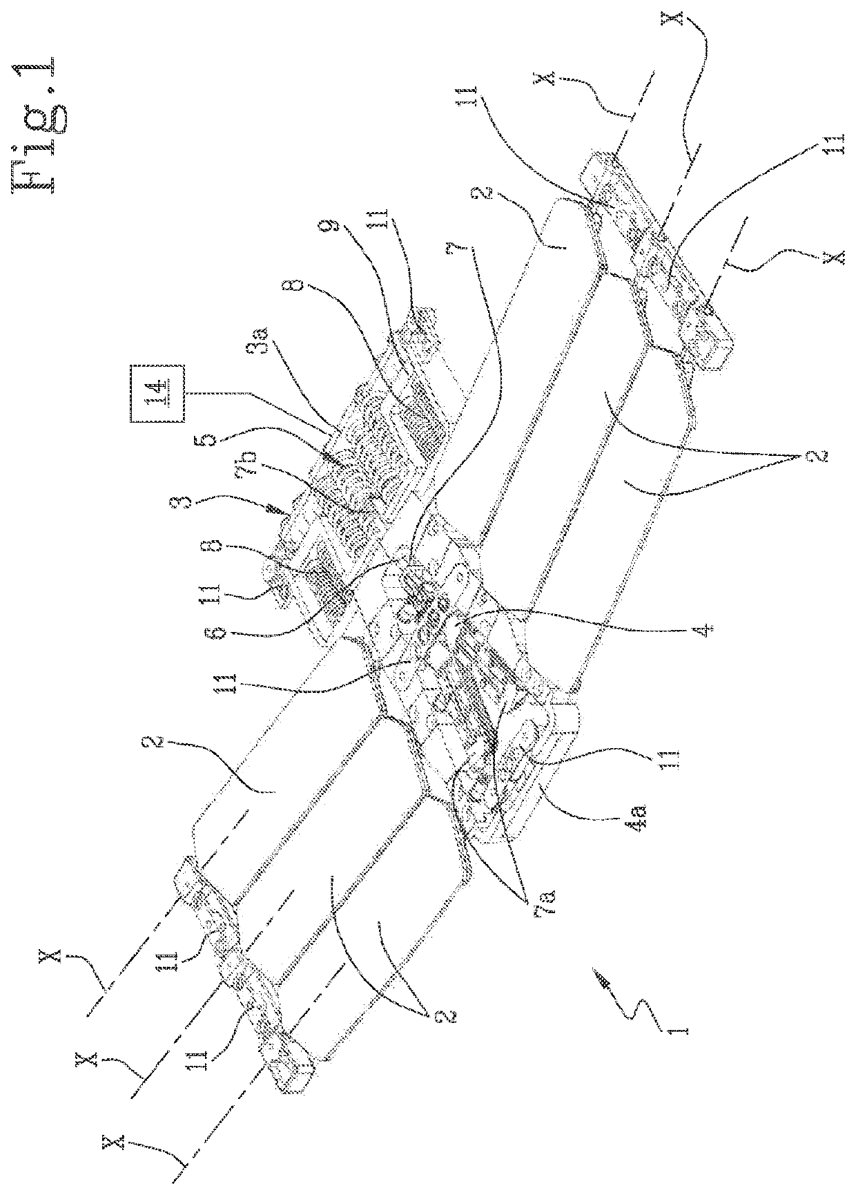
[0018]The numeral 1 in the accompanying drawings denotes in its entirety a device for regulating a cooling air flow in a vehicle, preferably a motor car, hereinafter referred to simply as “device 1”.

[0019]Generally speaking, the compartment is a delimited space which houses a car component that generates heat during its operation.

[0020]The compartment is, for example, the engine compartment and the component is the engine. In another example, the compartment is a brake cooling duct and the component is defined by the car brakes which are at least partly housed in or which face the duct.

[0021]Hereinafter, the engine compartment is expressly referred to as the preferred example of applying this solution but without thereby losing generality.

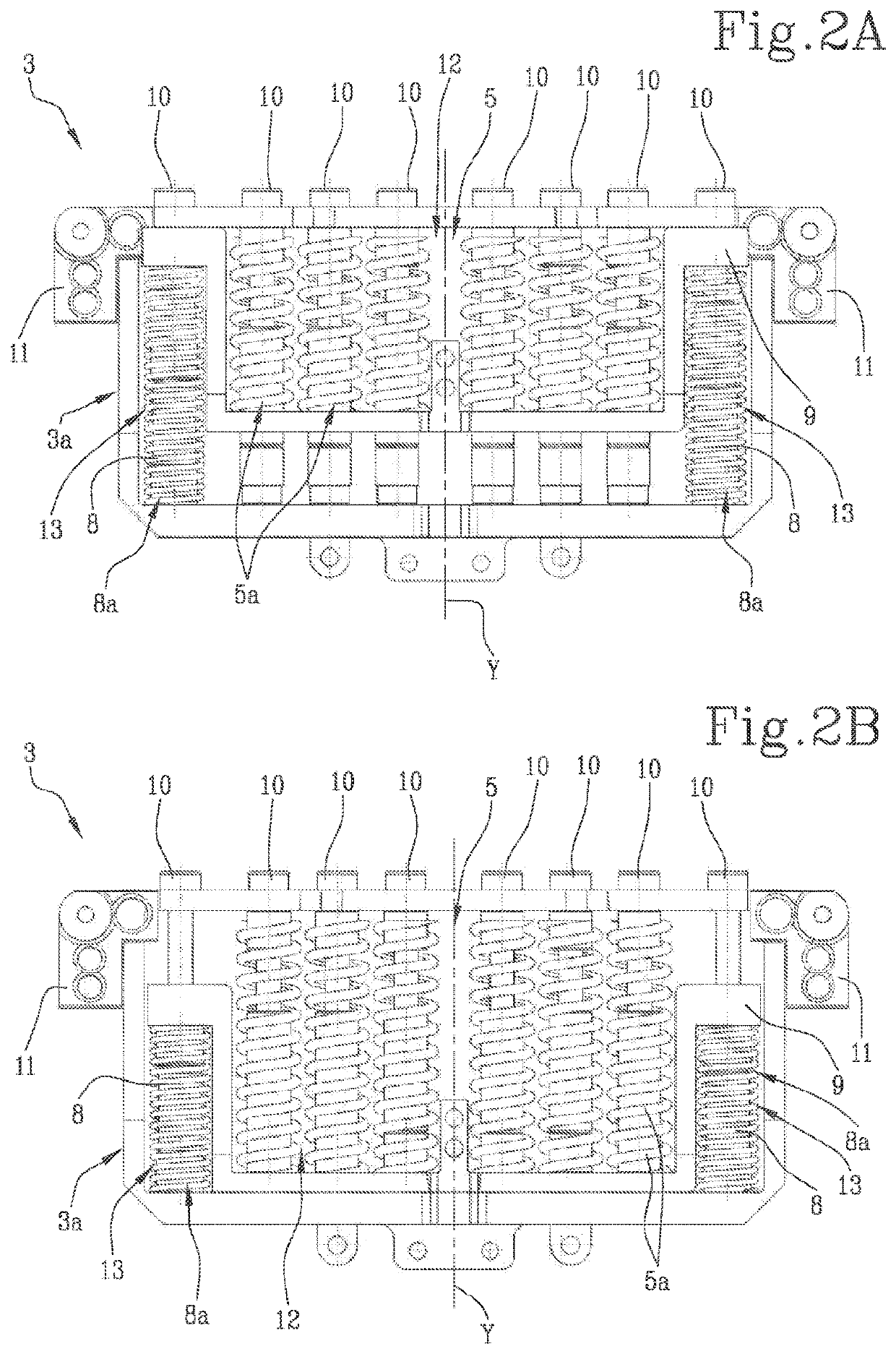
[0022]The device 1 comprises at least one wing 2, a drive module 3 and a transmission apparatus 4.

[0023]The wing 2 is connectable to an air flow opening of a compartment of a motor car, not illustrated, for example an engine compartment, and is mov...


PUM


Abstract

A device for controlling a hot air flow, for example in an engine compartment of a motor car, includes at least one wing connectable to an air inflow opening of an engine compartment of a motor car and movable between a position for closing and a position for opening the air inflow opening; a drive module configured to apply a predetermined thrust force and a transmission apparatus capable of transmitting the thrust force from the drive module to the wing to move the wing from the closed position to the open position and vice versa.The drive module includes at least one actuator made of a shape-memory alloy such that the thrust force is applied when the actuator reaches a predetermined temperature.

Description

TECHNICAL FIELD[0001]This invention addresses the automotive sector, in particular, a device for regulating and / or controlling a hot air flow generated by a component of a vehicle, specifically, a motor car during its operation.BACKGROUND ART[0002]Generally speaking, a vehicle comprises different components which, during their operation, generate heat inside the compartment or housing in which each is located.[0003]The typical example is the engine, which generates heat in the engine compartment; another example is the brakes, which generate heat that may be confined to a duct where the brakes are housed.[0004]During normal operation, a motor car engine generates a considerable amount of heat which, if not correctly dissipated, may lead to serious damage to the engine itself and to other vehicle parts and components adjacent to the engine, especially those located in the engine compartment.[0005]At the same time, the engine has to work at an optimum temperature of its own and the te...

Claims


Application Information

Patent Timeline
Patent Type & Authority Applications(United States)
IPC IPC(8): B60K11/08
CPCB60K11/085Y02T10/88
Inventor RICCIO, ANIELLORICCIO, UGOSELLITTO, ANDREATORLUCCIO, ANTONIO
Owner AUTOMOBILI LAMBORGHINI
Learn More