Method For Detecting Brake Circuit Failure

a technology of brake circuit and detection method, which is applied in the direction of brake control system, vehicle components, brake system, etc., can solve the problems of failure to detect, condition may go undetected, and failure to detect, so as to achieve the effect of generating zero or minimal pressure and avoiding failure to detect failur

Active Publication Date: 2008-10-09
KELSEY HAYES CO
View PDF11 Cites 26 Cited by
  • Summary
  • Abstract
  • Description
  • Claims
  • Application Information

AI Technical Summary

Benefits of technology

[0013]The present invention has the advantage of detecting a fault condition in a hydraulic braking system utilizing at least two hydraulic brake circuits and only one pressure sensor for a respective hydraulic brake circuit and for deactivating at least one assisted brake function in response to detecting said fault condition.

Problems solved by technology

For example, if the hydraulic brake failure is occurring, and the driver wants to stop immediately, the assisted braking cannot sense this issue or condition the driver is faced with and may attempt a vehicle stability control operation that is not in cooperation with the drivers intended braking operation.
If only one pressure sensor was utilized within a braking system utilizing two hydraulic brake circuits, then such a failure could go undetected.
However, without a second sensor (or other type of indicator) in the unsensed circuit for comparing the pressure within the two hydraulic brake circuits, a potential fault condition may go undetected and braking system would not recognize the drivers braking demands as the M / C pressure is zero in the sensed circuit.
However, zero or minimal pressure will be generated in the unsensed (failed) circuit, and as a result, only a portion of the vehicle braking would be applied.
Such braking function could potentially conflict with the driver's immediate braking demands.
Thus, in YSC systems, it is critical to utilize a pressure sensor in each hydraulic brake circuit, or other device (e.g., pressure differential switch) to detect the failure, however, the addition of a pressure sensor for each additional circuit in a braking system becomes costly.

Method used


Image

  • Method For Detecting Brake Circuit Failure
  • Method For Detecting Brake Circuit Failure
  • Method For Detecting Brake Circuit Failure

Examples


Embodiment Construction

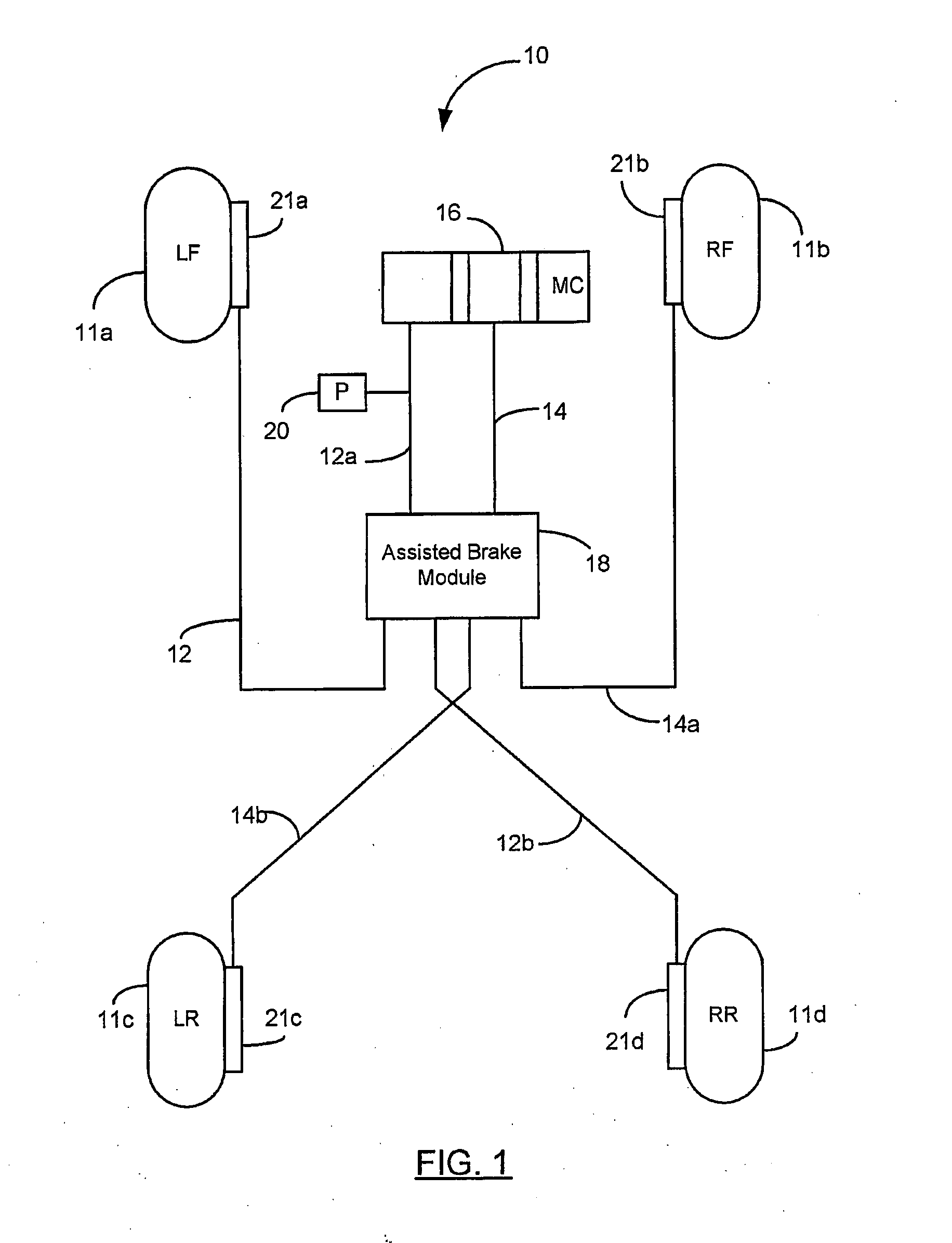
[0029]Referring now to the Drawings and particularly to FIG. 1, there is shown a schematic diagram of a hydraulic braking system for providing hydraulic brake fluid to a plurality of vehicle brake actuators. The hydraulic braking system is shown generally at 10. The hydraulic braking system 10 includes vehicle wheels 11a, b, c, and d. Vehicle brake actuators 21a, b, c, and d each include a respective brake actuation member (such as a slave cylinder) and friction member actuable by the actuation member for engaging a rotatable braking surface of the vehicle wheels 11a, b, c, and d, respectively. In the preferred embodiment, the vehicle braking system utilizes a diagonally split braking system. A first circuit of pressurized hydraulic brake fluid 12a and 12b (e.g., primary circuit) is provided for actuating vehicle brake actuators 21a and 21d. The second circuit of pressurized hydraulic brake fluid 14a and 14b (e.g., secondary circuit) is provided for actuating vehicle brake actuators...


PUM


Abstract

A method is provided for detecting a fault condition in a hydraulic brake system of a vehicle having a first hydraulic brake circuit and a second hydraulic brake circuit. A correlation ratio is determined between a measured pressure and the actual vehicle acceleration. A first wheel velocity differential is determined and a second wheel velocity differential is determined. A weighting value is selected in response to determining whether the correlation ratio is within the predetermined range and whether the first wheel velocity differential and the second wheel velocity differential are opposite signs. The selected weighting value is added to a fault counter. A determination is made whether the fault counter is equal to or greater than a predetermined threshold. A fault condition is detected in response to the fault counter greater than or equal to the first predetermined threshold.

Description

CROSS REFERENCE TO RELATED APPLICATIONS[0001]This application claims priority to U.S. Non-Provisional Application Ser. No. 10 / 928,800, filed Aug. 27, 2004, the disclosure of which is incorporated herein by reference.STATEMENT REGARDING FEDERALLY SPONSORED RESEARCH[0002]Not Applicable.BACKGROUND OF THE INVENTION[0003]1. Field of the Invention[0004]The present invention relates in general to detecting a hydraulic brake circuit failure within a split vehicle braking system, and more particularly, to detecting a hydraulic brake circuit failure while requiring a pressure sensor in only one of the two hydraulic brake circuits.[0005]2. Description of the Related Art[0006]Vehicle braking systems commonly include a master cylinder and reservoir for providing pressurized brake fluid to hydraulic brake circuits for actuating vehicle brakes. Vehicle braking systems typically include two hydraulic brake circuits for actuating a respective set of vehicle brakes. During vehicle stability control m...

Claims


Application Information

Patent Timeline
Patent Type & Authority Applications(United States)
IPC IPC(8): B60T8/88
CPCB60T8/885B60T2270/403B60T2270/413
Inventor SPIEKER, ARNIELUBBERS, MARK D.O'CONNOR, MICHAEL
Owner KELSEY HAYES CO
Why Eureka
Try Eureka