Field configurable magnetic array

a magnetic array and field technology, applied in the field of magnetic arrays, can solve the problems of power permanent, difficult to achieve monolithic composite high-power “hard” magnet concentric patterns, and high power required to magnetize a concentrically arranged high-power permanent magnet such as neodymium iron boron, so as to reduce the blending of opposite fields and increase the field projection of active magnet zones.

Inactive Publication Date: 2008-10-09
SOUDER JAMES J +1
View PDF9 Cites 17 Cited by
  • Summary
  • Abstract
  • Description
  • Claims
  • Application Information

AI Technical Summary

Benefits of technology

[0014]Another embodiment according to the present invention comprises a concentric array of multiple high power magnets having a moat or a zone of magnetically transparent material positioned in between adjacent high power magnets such that flux returning around a periphery of a magnet will exert around the periphery of a magnet will exert minimum cancellation or reinforcement of flux exiting the plane of the adjacent magnets. In the case of like pole neighboring magnets, there will be mutual cancellation of the proximal zones, and the moat will appear to be a zone of opposite polarity. In the case of a moat placed between elements of opposite polarity, the result will be increased field projection of the active magnet zones due to diminished blending of opposite fields above the surface of the array.

Problems solved by technology

The problem with that method is that the power required to magnetize a concentrically arranged high power permanent magnet such as neodymium iron boron is too high.
Monolithic composite high power “Hard” magnet concentric patterns are difficult to achieve, because it is not practical using current technology to impress concentric magnetic zones of opposite polarity onto a wafer of homogeneous high power magnet material such as neodymium iron boron.
A technical obstacle present when constructing concentric patterns of a multi-element single pole array using high power permanent magnets is that magnetic disks of like polarity in the same plane mutually repel each other.

Method used


Image

  • Field configurable magnetic array
  • Field configurable magnetic array
  • Field configurable magnetic array

Examples


Embodiment Construction

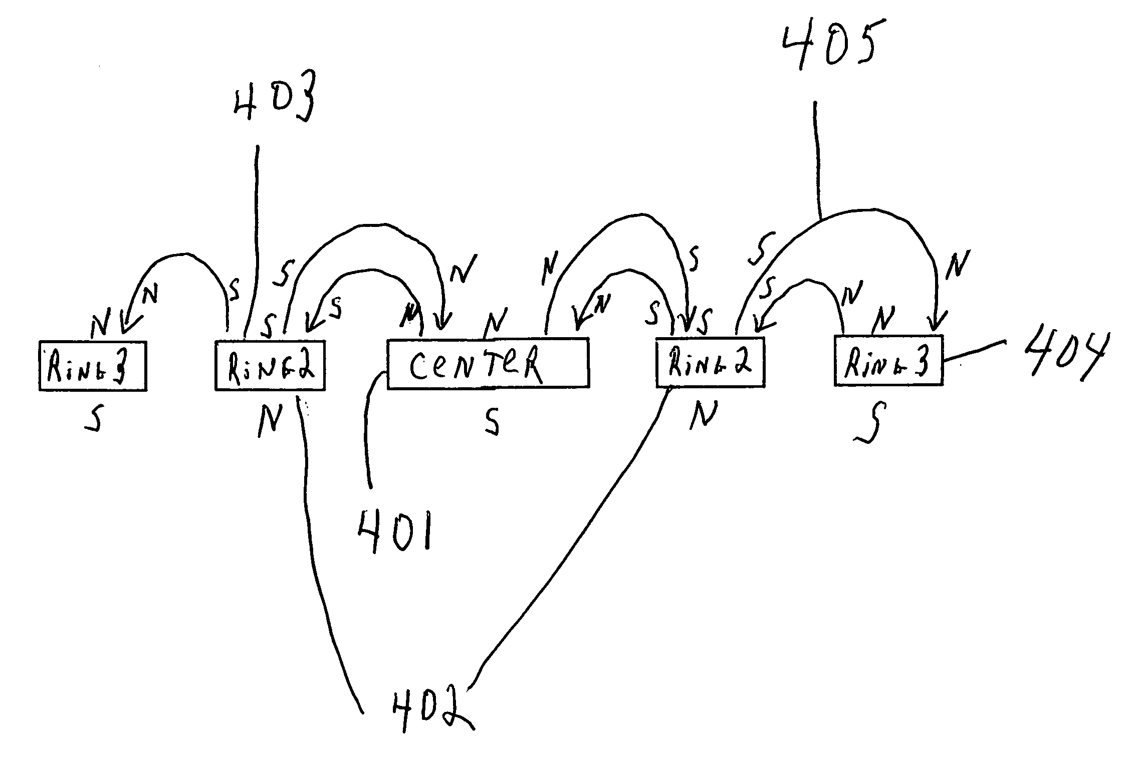
[0036]The apparatus according to present invention comprise adjacently or concentrically configuring a plurality of high power permanent magnets such that the array can deliver more flux per unit volume and can deliver optimum penetration characteristics.

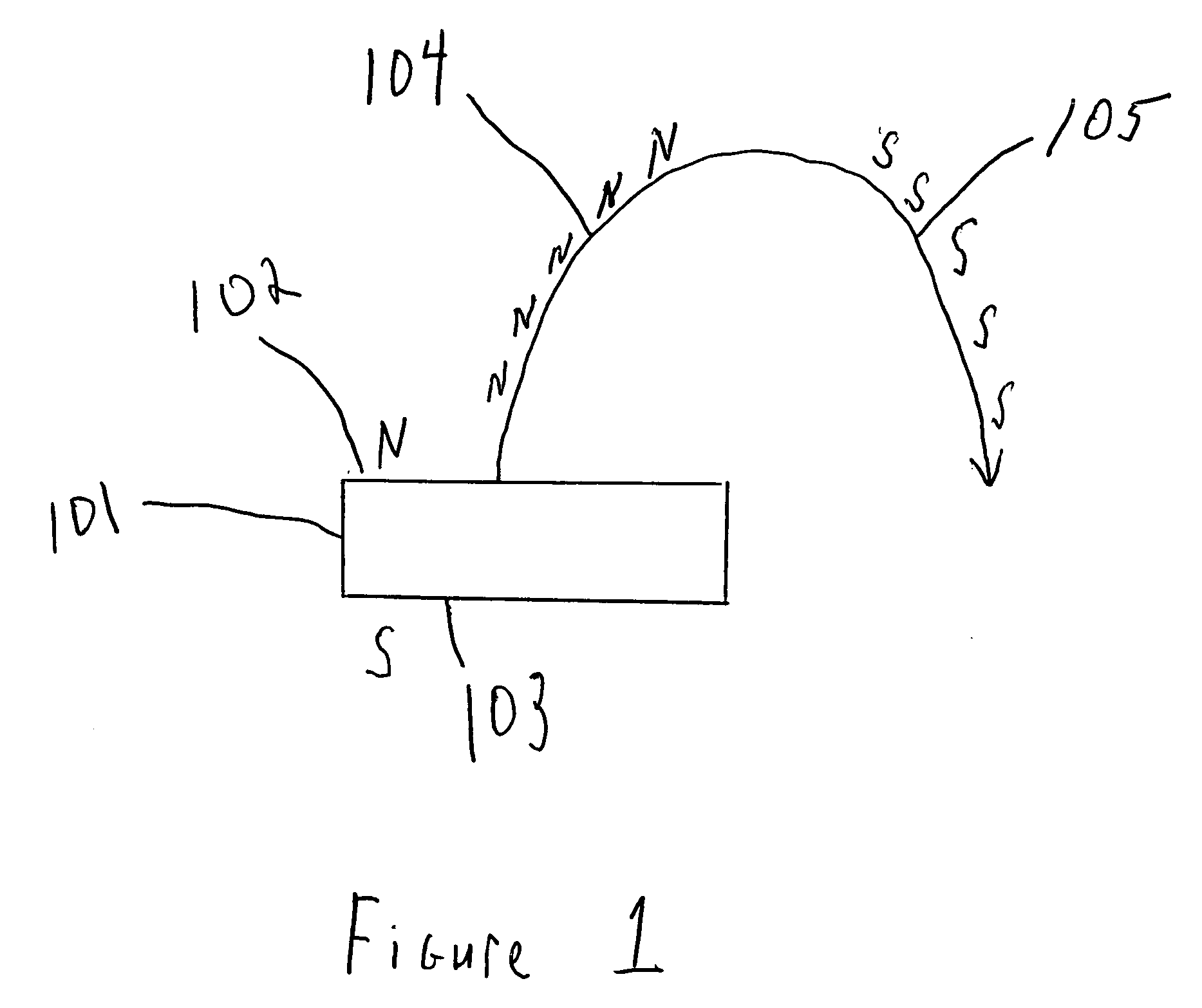
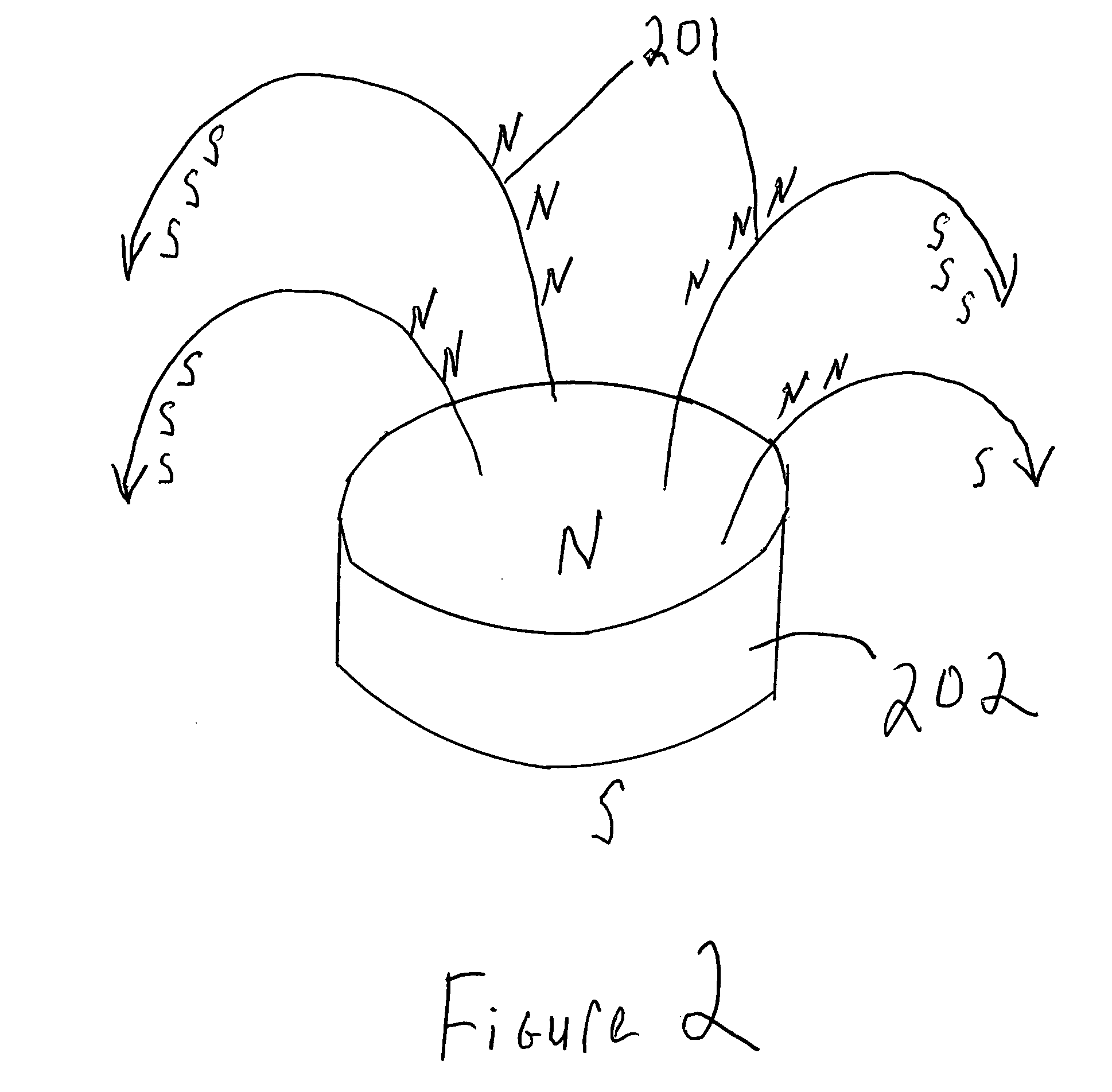
[0037]The benefits of concentric circle magnet arrays are believed by many practitioners to derive from blood vessels crossing over zones of opposite polarity. Additionally a concentric pattern is an ideal geometric pattern to permit a pole arrangement where the flux emanating from a central pole magnetic element or any given orbital ring can arc over on the arched trajectory of a flux line and descend on a magnetic element adjacent to it. After the flux reaches its apex it returns toward the plane from which it originated. When the flux returns to the plane from which it originated it is now going in the opposite direction. Thus a Gauss meter would ascribe the zone it travels through on the downward portion of the arc as having a p...


PUM

PropertyMeasurementUnit
thicknessaaaaaaaaaa
thicknessaaaaaaaaaa
sizeaaaaaaaaaa

Abstract

A magnet apparatus comprising a plurality of geometrically shaped nested magnetic elements each being of a different size relative to each other and each having a first side with a first magnetic pole orientation and a second side with a second magnetic pole orientation that is opposite to the first magnetic pole orientation, capable of being assembled concentrically to form a single planar magnet array having a treatment surface and an opposing backer surface, the treatment surface having either an all like magnetic pole orientation or a mixed magnetic pole orientation; and a backer plate having a first side and a second side constructed of ferromagnetic material such that when the plurality of geometrically shaped nested magnetic elements is assembled concentrically on the first side of the backer plate each of the geometrically shaped nested magnetic elements that comprise the single planar magnet array is secured to the first side of the backer plate by magnetic attraction whereby the treatment surface of the single planar magnet array is formed opposite to the backer surface of the single planar magnet array that is magnetically secured to the backer plate.

Description

[0001]This application claims the benefit of U.S. Provisional Application 60 / 586,830 filed Jul. 9, 2004 herein incorporated by reference in its entirety.BACKGROUND OF THE INVENTION[0002]1. Field of the Invention[0003]The present invention relates to magnet arrays that are used to deliver magnetic therapeutic fields to tissue in plants and animals. In particular a plurality of discrete shaped magnetic elements can be combined to form a single magnet array comprising discrete magnetic zones which may be of like polarity or mixed polarity. The overall polarization of the single magnet array can be varied by positioning the poles of each of the magnetic elements to be either North or South. Thus to obtain like polarity in the magnet array the polarity of each of the magnetic elements that comprise the array would be positioned to either North or South. Another embodiment according to the present invention comprises moats or spacer elements of non-magnetic material positioned in between ...

Claims


Application Information

Patent Timeline
Patent Type & Authority Applications(United States)
IPC IPC(8): H01F7/02
CPCA61N2/008A61N2/06H01F7/0294H01F7/0221
Inventor SOUDER, JAMES J.ZABLOTSKY, CHARLES
Owner SOUDER JAMES J
Why Eureka
Try Eureka