Phased array antenna formed as coupled dipole array segments

a dipole array and phased array technology, applied in the field of communication, can solve problems such as increasing the length of fingers

Inactive Publication Date: 2008-10-09
HARRIS CORP
View PDF11 Cites 31 Cited by
  • Summary
  • Abstract
  • Description
  • Claims
  • Application Information

AI Technical Summary

Problems solved by technology

Increasing the length of fingers, however, can be problematic because the structure becomes resonant.

Method used


Image

  • Phased array antenna formed as coupled dipole array segments
  • Phased array antenna formed as coupled dipole array segments
  • Phased array antenna formed as coupled dipole array segments

Examples


Embodiment Construction

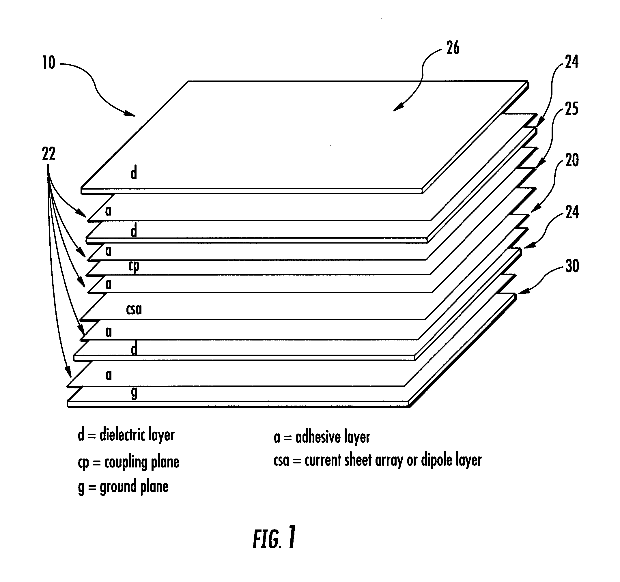
[0022]Different embodiments will now be described more fully hereinafter with reference to the accompanying drawings, in which preferred embodiments are shown. Many different forms can be set forth and described embodiments should not be construed as limited to the embodiments set forth herein. Rather, these embodiments are provided so that this disclosure will be thorough and complete, and will fully convey the scope to those skilled in the art. Like numbers refer to like elements throughout.

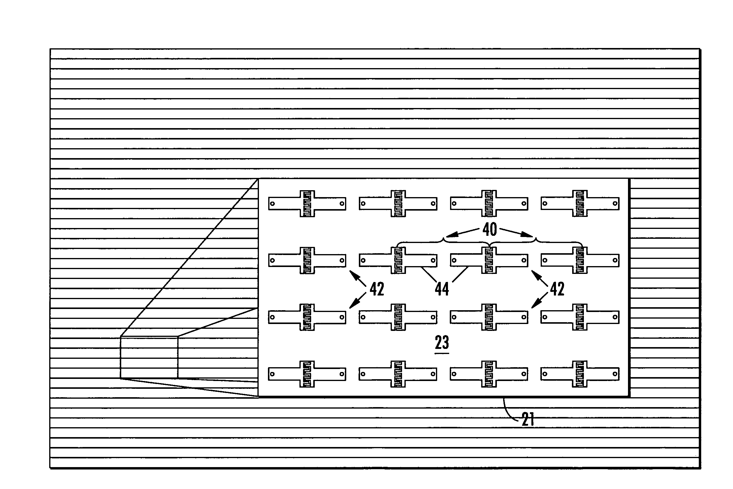
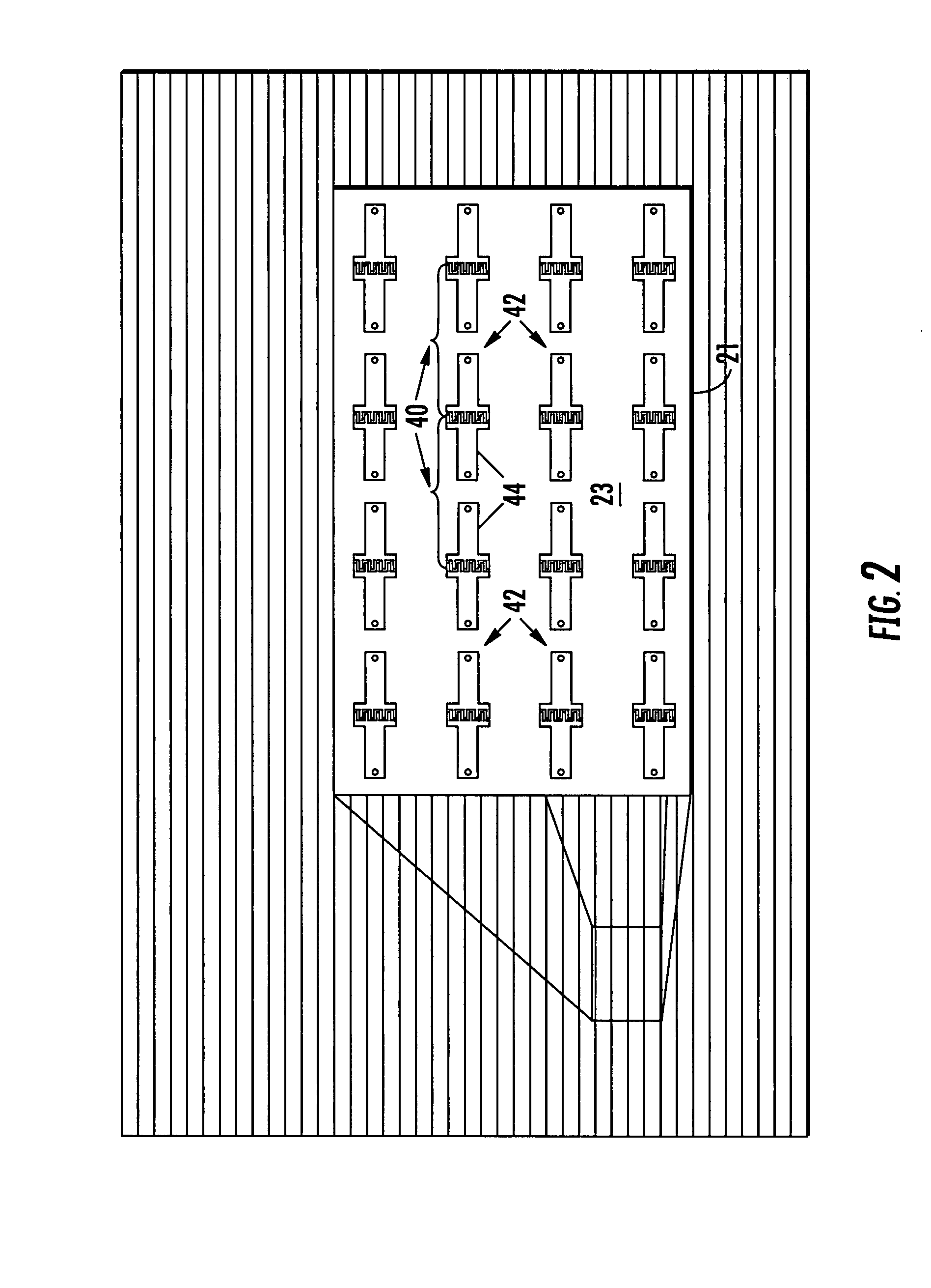
[0023]A phased array antenna, in accordance with a non-limiting example of the present invention, overcomes the problems associated with a construction where no acceptable cut-lines can segment the antenna structure to form array “tiles,” which would allow the array to be more easily manufacturable and repairable. For example, it is not possible to cut through any feed point (feed lines) because this is a sensitive area of the antenna where feed characteristics and impedances are important. Any...


PUM


Abstract

A phased array antenna includes a substrate that is segmented into a plurality of array tiles. An array of dipole antenna elements is formed on the substrate with each dipole antenna element positioned on a respective one of the array tiles. Each dipole antenna element includes a medial feed portion and a pair of legs extending outwardly therefrom. Adjacent legs of adjacent dipole antenna elements include respective spaced apart end portions forming a gap between the respective end portions and defined by separate tiles. A capacitor coupler is positioned at each respective spaced apart end portion of adjacent legs and bridging a gap for capacitive coupling respective spaced apart end portions of respective adjacent dipole antenna elements together.

Description

FIELD OF THE INVENTION[0001]The present invention relates to the field of communications, and more particularly, the present invention relates to phased array antennas.BACKGROUND OF THE INVENTION[0002]Lightweight phased array antennas having a wide frequency bandwidth and a wide scan angle can be economically manufactured and conformally mounted on a surface, such as a nose cone of an aircraft. Examples of such antenna include a current sheet array (CSA) formed of at least one dipole layer and using coupling capacitors between antenna dipole elements. The capacitors often are formed as interdigitated “fingers.” The coupling capacitance between dipole elements can be increased by lengthening the capacitor “digits” or “fingers,” which results in additional bandwidth for the antenna. An example of this type of structure is disclosed in commonly assigned U.S. Pat. No. 6,417,813 to Durham, the disclosure which is hereby incorporated by reference in its entirety.[0003]A similar phased arr...

Claims


Application Information

Patent Timeline
Patent Type & Authority Applications(United States)
IPC IPC(8): H01Q9/16H01Q21/00
CPCH01Q9/285H01Q9/36H01Q21/00
Inventor RAWNICK, JAMES J.TRENT, CHRISTOPHER
Owner HARRIS CORP
Why Eureka
Try Eureka