Optical system for a wash light

a technology of optical systems and wash lights, applied in optics, lighting devices, instruments, etc., can solve the problems of high efficiency of systems, undesirable high and high beam intensity of systems, so as to avoid excessive intensity in the beam centre and avoid intensity loss

Inactive Publication Date: 2008-10-09
ROBE SHOW LIGHTING S R O
View PDF12 Cites 6 Cited by
  • Summary
  • Abstract
  • Description
  • Claims
  • Application Information

AI Technical Summary

Benefits of technology

[0012]At a first limit position when the optical system is adjusted so as to provide the minimum beam divergence and the first and second optical elements are maximally separated the semicircular diffusers are completely outside the aperture in the first optical element and the light beam will pass through the aperture with no intensity loss. In this configuration the first optical element has practically no effect on the beam. At a second limit position when the optical system is adjusted so as to provide the maximum beam divergence and the first and second optical elements are minimally separated the semicircular diffusers completely occlude the aperture in the first optical element and thus diffuse the central illumination so as to avoid excessive intensity in the beam centre.

Problems solved by technology

Various optical systems are well known in the prior art for providing this beam angle control; however, they all suffer from various disadvantages and concerns.
Such systems are capable of a large range of adjustment of the output beam angle but are highly inefficient systems, particularly at narrow beam angles where much of the light from the light source and reflector completely misses the output lens.
Such a system is described in U.S. Pat. 6,899,451 to Kittelmann et al. however the beam produced by this system is prone to having a very high intensity in the centre, often known as a hot-spot, which is undesirable for many uses.
As with the systems above this produces an undesirable high intensity in the beam centre, or hot-spot particularly when used at narrow beam divergence.
In addition the use of two lenses rather than one reduces the overall efficiency of the system.

Method used


Image

  • Optical system for a wash light
  • Optical system for a wash light
  • Optical system for a wash light

Examples


Embodiment Construction

[0022]Preferred embodiments of the present invention are illustrated in the FIGUREs, like numerals being used to refer to like and corresponding parts of the various drawings.

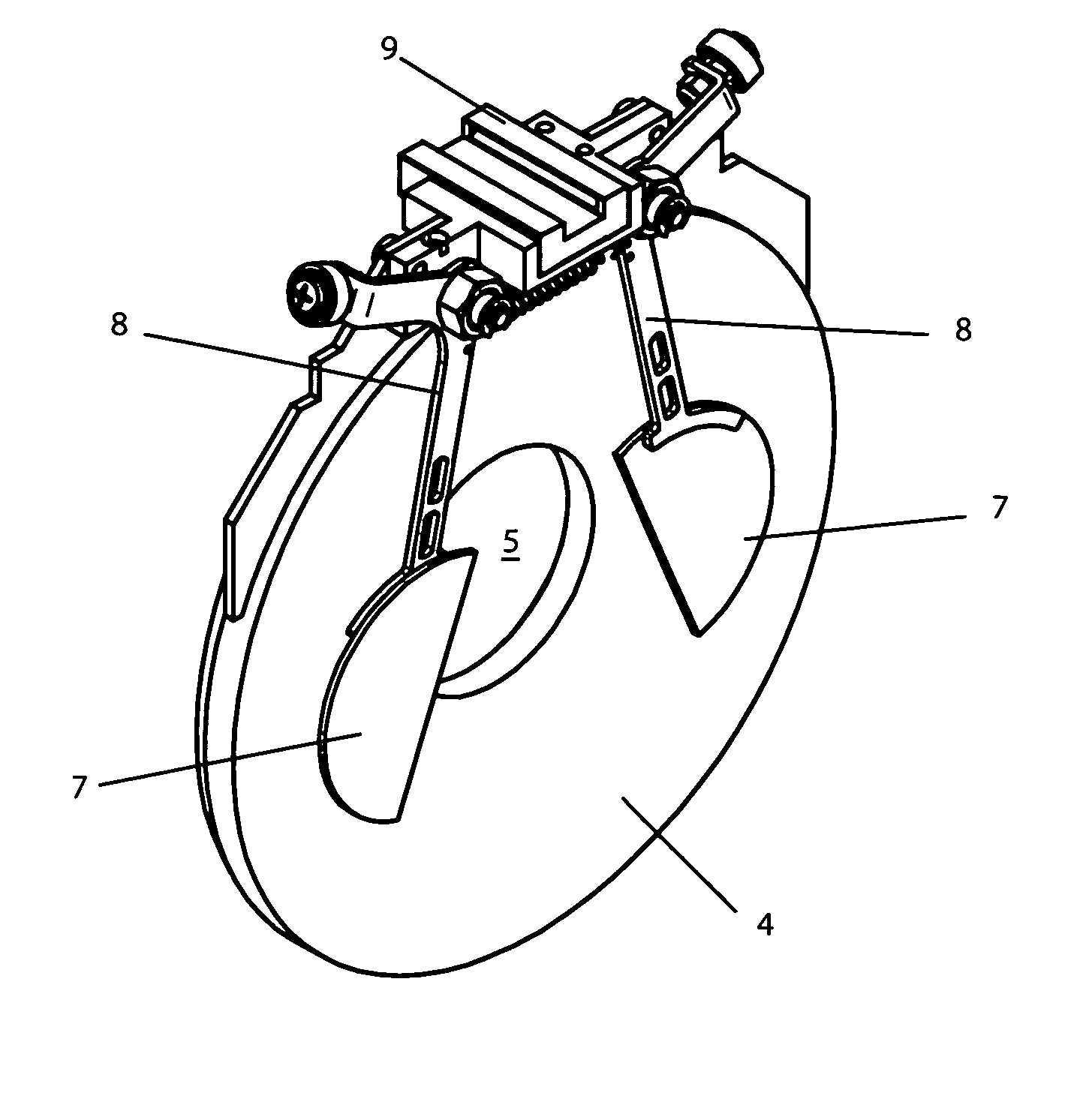
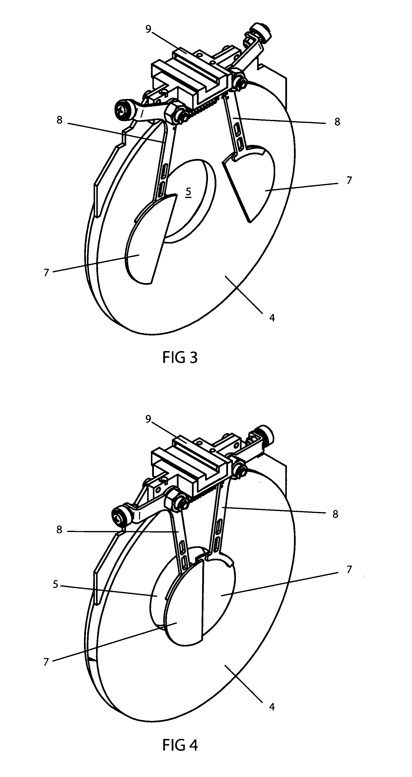
[0023]The present invention generally relates to an optical system for a luminaire for producing a light beam. The optical system is particularly used for a category of luminaire known as a wash light and specifically to a variable beam angle wash light which provides an improved range of beam angles balanced with size and efficient light output.

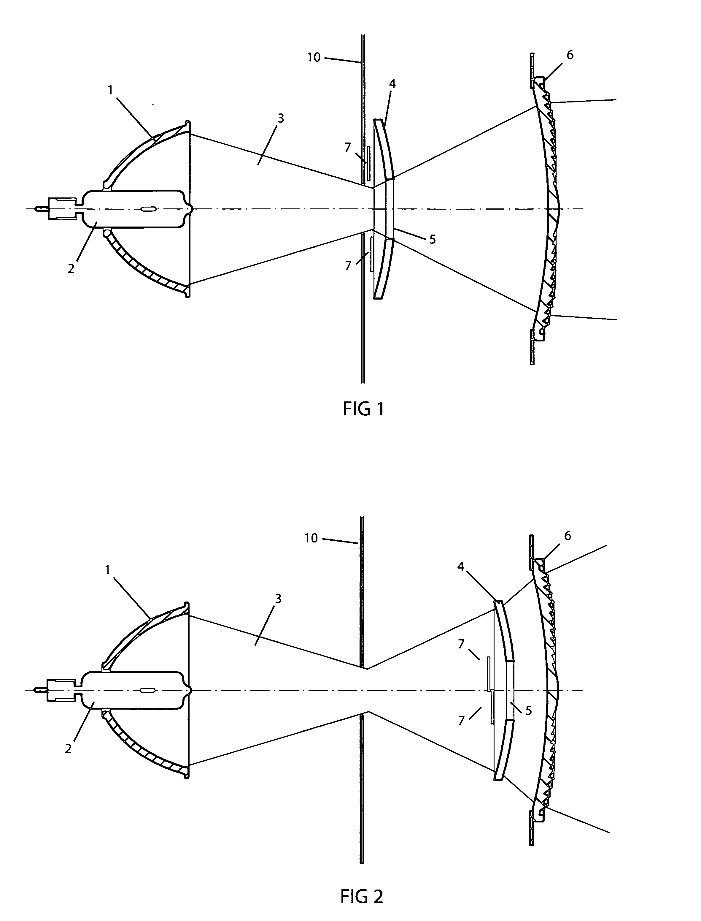
[0024]FIG. 1 illustrates a plan view along the optical axis of the optical path of an embodiment of the present invention. In FIG. 1 the optical elements are shown in a configuration which provides for minimum beam divergence (a narrow beam angle). The embodiment illustrated in FIG. 1, including the lamp, employs the use of six optical elements. The first element, a lamp 2, provides the light source which is positioned close to the first focus of elliptical reflector 1,...


PUM


Abstract

The present invention generally relates to an optical system for a wash light and specifically to a variable beam angle system which provides an improved range of beam angles and efficient light output. The present invention includes a light modulating optical element that has a central aperture that can be moved along the optical axis the system. Further the central aperture of the modulating element may be occluded by a diffusing element. The extent of the occlusion can be varied. At a first limit position when the optical system is adjusted so as to provide the minimum beam divergence the light beam will pass through the aperture with no intensity loss. In this configuration the first optical element has practically no effect on the beam. At a second limit position when the optical system is adjusted so as to provide the maximum beam divergence the diffusers cover the central aperture to diffuse the central illumination so as to avoid excessive intensity in the beam centre. The range of beam angles and light modulation can be further improved by means of a variable sized aperature.

Description

RELATED APPLICATION[0001]This application is a continuation in part application of application Ser. No. ______ (not yet assigned) filled on Mar. 11, 2008 which is a National Phase application of PCT Application Number PCT / CZ2006 / 000011 filed on Mar. 3, 2007.TECHNICAL FIELD OF THE INVENTION[0002]The present invention generally relates to optical systems. More specifically optical systems in a light beam producing luminaire, particularly for a wash light and even more specifically to a variable beam angle wash light system which provides an improved range of beam angles and efficient light output.BACKGROUND OF THE INVENTION[0003]Luminaires used in the entertainment industry such as those commonly used in theatres, television studios, concerts, theme parks, night clubs and other venues can typically be broadly categorized into two main categories each with differing optical properties. The two categories are imaging and non-imaging. The imaging type (commonly known as spot lights) are ...

Claims


Application Information

Patent Timeline
Patent Type & Authority Applications(United States)
IPC IPC(8): G02B26/08
CPCF21V11/18F21W2131/406
Inventor JURIK, PAVEL
Owner ROBE SHOW LIGHTING S R O
Why Eureka
Try Eureka