In fact, at
room temperature—indeed, at any temperature below the
Curie temperature of the
magnetic alloy used to form the storage layer (the
Curie temperature is generally in the range of 200 to 300 degrees centigrade for the magnetic alloys commonly employed in MO discs)—unattainably large external magnetic fields would be required to switch the
magnetic orientation of the storage layer's domains.
There are many sophisticated methods of accomplishing this, which are commonly applied and well known in the art (particularly in reference to data storage on computer hard drives), but which are not directly relevant to the present discussion.
Furthermore, because this layer has some finite
heat capacity, it takes time for the film to cool after it is heated to its
Curie temperature.
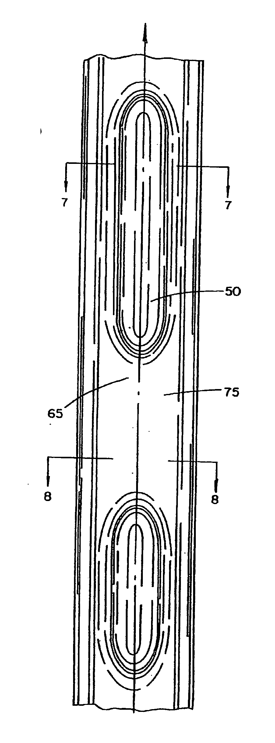
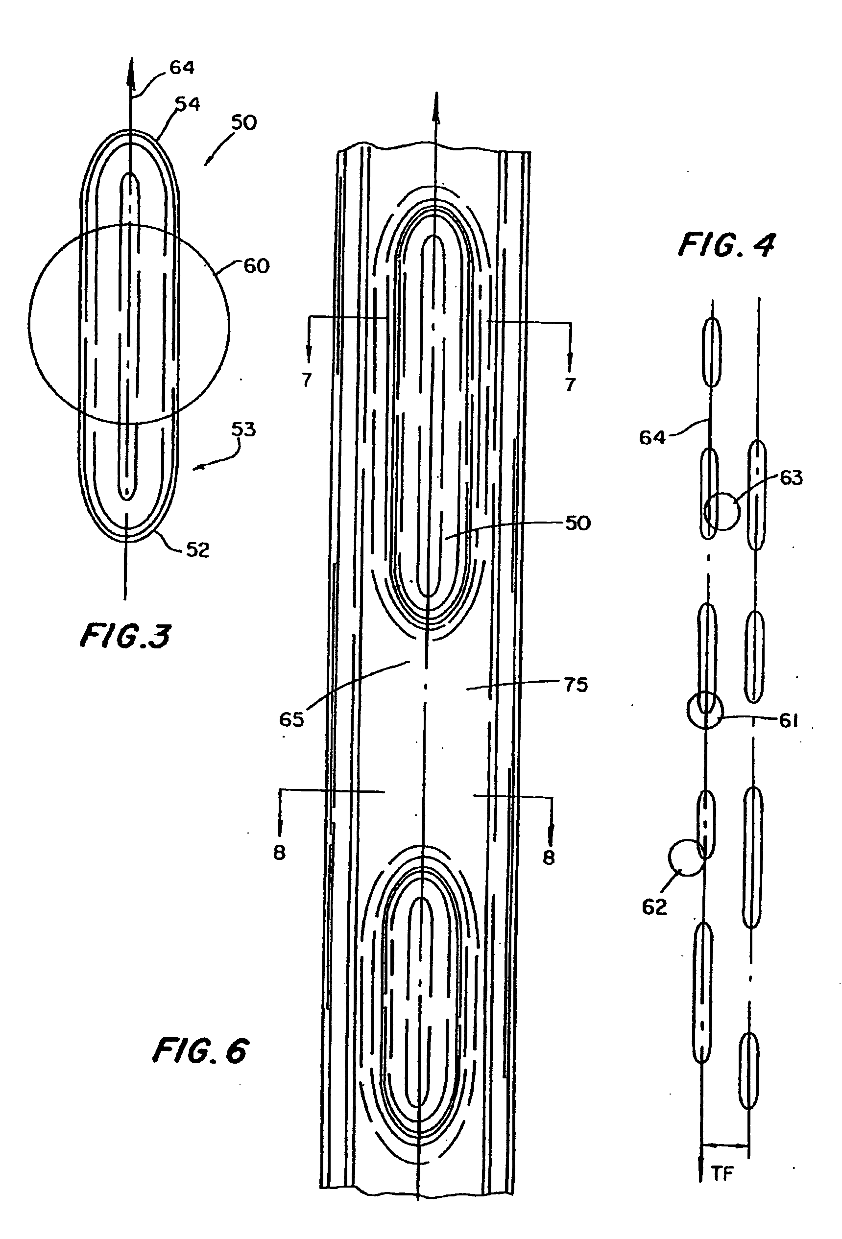
Also, since the transverse extent of the formed mark is limited by the pre-groove's sidewalls, bloom is mostly a problem in the longitudinal (along the track) direction.
While the Feyrer Patent PC teachings might, at first glance, appear to be applicable to disc mastering, the complex bonding processes and the nature of the materials necessitated by the Feyrer
dual layer concept would not be conducive to commercially-practical, accurate disc mastering and replication.
But by the same token, a PR disc cannot conveniently be erased and re-written, and PR is therefore inapplicable to the chief purposes of the MO and PC methods: erasable / re-writable data storage.
However, as a general principle it is accurate to say that increasing the incident intensity will tend to increase the depth of
exposure within the
photoresist medium.
However, where
data retrieval at extremely rapid hard drive acquisition rates is not essential—for example, in most CD-ROM and DVD-ROM applications—the introduction of necessary decoding logic to account for different data mark lengths corresponding to identical data values, depending on radial distance, may not be justified.
Failure to fully
expose the
photoresist (resulting in residual
photoresist at the bottom of the pit) has been found generally to produce “noisy” data output readings, because of inherent roughness in the etched photoresist layer and greater susceptibility to recording
laser noise.
These compromise detection accuracy, because pit and land playback
signal amplitude is affected by surface characteristics.
Less stringent controls can yield a stamper that is a reasonably good
mirror image of the master, but replicated discs whose reproduced pits do not exactly reproduce the cross-sectional shape of those in the master.
The latter is typically the result of imprecise molding methods, yielding replicated disc pits whose cross-sectional shapes in the radial direction display rounded corners, rather than the normally crisply angular corners of the master disc pits.
Regardless of the particular application, the PR method is essentially an
etching process, and a certain amount of roughness occurs on the pit sidewall surfaces is thus inevitable.
While this has not proved to be a particularly significant problem in CD mastering applications, where
data retrieval is essentially
diffraction-interference based, the PR method of disc mastering appears not entirely conducive to production of DVD masters from which commercial DVD-ROM's can be rapidly manufactured with a low
rejection rate.
The inherent roughness of PR-generated data pits impedes accurate DVD
data retrieval.
Furthermore, this problem of roughness in PR-generated disc masters can only become more troublesome as data densities increase beyond the present DVD-ROM level of approximately 4.2 gigabytes per data layer, and data retrieval strategies necessarily become more sophisticated.
When this occurs, the inherent roughness of PR-generated disc masters may further limit their utility.
The characteristic roughness, and the fact that PR-generated pits are normally rather steep-sided and display angular corners, also result in certain difficulties in separation of
daughter discs from the stampers by which they are reproduced.
In all probability, it may not be possible to completely eliminate them.
However, this is not generally done, for the reasons briefly explained above.
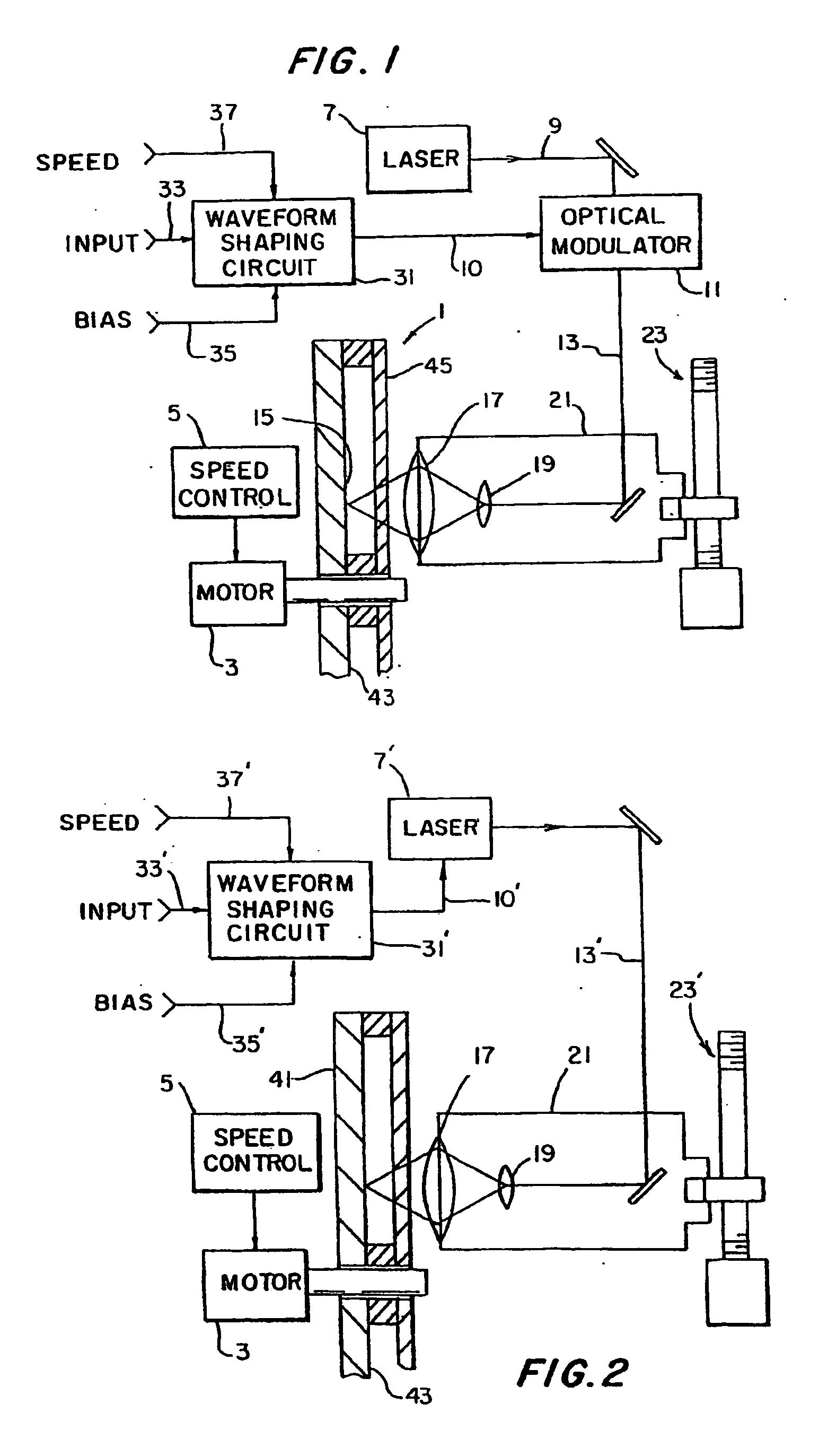
However, if a
gas laser is employed, external modulation must normally be employed, since gas lasers typically cannot react to input fluctuations as rapidly as can
solid state lasers.
This “thermal smearing” affects the size and shape of the recorded pit.
Unfortunately, this is complicated by the fact that the criteria inherent in accurate data retrieval (
high frequency, “HF”) detection and in accurate push-pull (“PP”) tracking, required in all pre-recorded CD applications, are mutually exclusive.
But the two processes are inherently opposed.
However, because this is accomplished by reducing the write beam intensity to near the
thermal threshold, the resulting land groove must necessarily be quite narrow.
But this actually compromises PP detection, because optimal PP detection is realized with a groove that is wider than one that would optimize HF detection.
Furthermore, HF detection is not significantly addressed by Schoofs.
But that would compromise PP detection by deepening the groove and would also compromise HF detection by causing pit / land transitions to be more difficult to detect, thus negatively counterbalancing the proposed PP improvements in the overall
Figure of Merit.
But there are several fundamental problems with either of those teachings—which are both based on the PR optical
data recording method: (1) it is difficult to consistently produce slope-sided pits by the PR method, which is essentially an
etching process and which, therefore, tends to generate pits whose sides are perpendicular to the disc surface; (2) slope-sided, PR-generated pits will
expose more of their characteristic roughness (i.e., noisiness) to the HF
detector, which makes DVD and ultra-
high density data retrieval difficult; yet (3) pits whose sides are perpendicular to the disc surface increase the previously discussed problem of difficult stamper-replica separation.

