Sweet Spot Beam Splitter for Separating Images

a beam splitter and beam beam technology, applied in the field of image separation, to achieve the effect of improving the ability of untracked displays and enlargement of sweet spots

Inactive Publication Date: 2008-10-09
SEEREAL TECHNOLOGIES
View PDF8 Cites 28 Cited by
  • Summary
  • Abstract
  • Description
  • Claims
  • Application Information

AI Technical Summary

Benefits of technology

[0019]Thanks to the enlargement of the sweet spots with the help of the image separation system according to this invention, a number of disadvantages of autostereoscopic displays are remedied at the same time. A viewer can move laterally in a sweet spot in the viewing space without losing the 3D impression. The corresponding mobility range is limited to one eye distance. It is thus sensible to choose a sweet spot extension of an eye distance of a viewer, i.e. about 65 mm. However, larger sweet spots are possible. They perform as well as long as the sweet spots for the right and left eye do not overlap.
[0020]With untracked autostereoscopic displays, lateral and normal movements, i.e. movements which affect the distance between viewer and display, are thus preferably possible in a sweet spot without the occurrence of cross-talking, e.g. pseudoscopic effects, due to the changed position of the viewer. This also improves the ability of untracked displays to support multiple users.

Problems solved by technology

Further, a limited dimensioning ability of the projection system following the image matrix in the flat display shall be taken into account.

Method used


Image

  • Sweet Spot Beam Splitter for Separating Images
  • Sweet Spot Beam Splitter for Separating Images
  • Sweet Spot Beam Splitter for Separating Images

Examples


Embodiment Construction

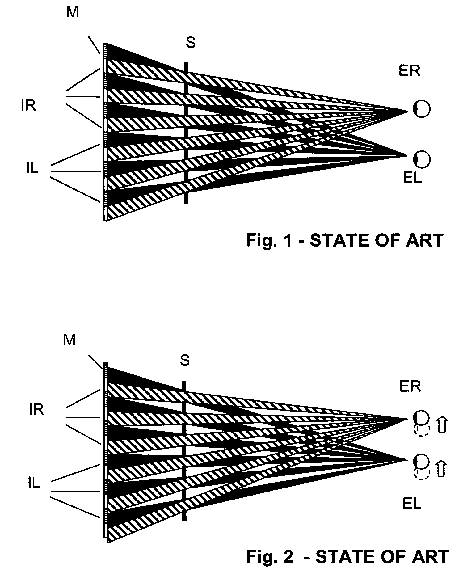
[0039]FIGS. 1 and 2 illustrate schematically the prior art image projection in an untracked autostereoscopic display with image matrix and conventional beam splitter. FIG. 1 is a schematic diagram which illustrates the prior art image projection in an untracked autostereoscopic display with image matrix and conventional beam splitter.

[0040]Seen in the direction of light propagation, FIG. 1 shows one after another an image matrix M, a conventional beam splitter S and the left eye EL and the right eye ER of a viewer. The image matrix M contains a right and a left stereo image IR and IL, which are interleaved alternately in columns. The sweet spot which carries the image information only has the extension of a point or vertical line. If the viewer's eyes are precisely in these sweet spots, he will perceive a stereo image without cross-talking. The right eye can only see the right stereo image, and the left eye can only see the left stereo image.

[0041]FIG. 2 is a schematic diagram which...


PUM


Abstract

The invention relates to an optical imaging system for separating images, more specifically a sweet spot beam splitter, for an autostereoscopic display, which allows for greater freedom of movement of at least one observer in a lateral direction as well as regarding the distance from the display by expanding sweet spots up to and beyond the size corresponding to the distance between the eyes. The observer can move within said area without losing the 3D impression such that the demands on the positional accuracy and the reaction time of the tracking system are lowered. The inventive sweet spot beam splitter comprises a first lenticular system (L1) and a second lenticular system (L2), the strip-shaped lenses of which are disposed parallel to each other while being offset by half a lens width in a vertical direction relative to the columns of the image matrix (M). The distance therebetween preferably corresponds to the focal length of the second lenticular system (L2). The information-carrying columns of the image matrix (M) are reproduced at twice the width onto the strip lenses of the second lenticular (L2) by means of the first lenticular system (L1). The invention allows the user-friendliness of autostereoscopic displays to be substantially improved in many applications.

Description

CROSS REFERENCE TO RELATED APPLICATIONS[0001]This application claims the priority of PCT / DE2004 / 001911 filed on Aug. 30, 2004, and DE 103 40 089.3 filed on Aug. 30, 2003, the entire contents of which are hereby incorporated in total by reference.BACKGROUND OF THE INVENTION[0002]The present invention relates to an optical projection system for image separation in an autostereoscopic display which offers the viewers the possibility of greater mobility and which consists of two lenticulars with vertical strip lenses, which are arranged parallel to each other in the optical path, where the lenticulars are disposed behind an image matrix, seen in the direction of light propagation.[0003]Autostereoscopic displays require left and right image information to be separated spatially through an optical projection system. Such optical projection systems are often referred to as beam splitters. The present invention relates to an autostereoscopic display with beam splitter and the representation...

Claims


Application Information

Patent Timeline
Patent Type & Authority Applications(United States)
IPC IPC(8): G02B27/10G02B27/22G03B35/24H04N13/00
CPCH04N13/0404H04N13/305H04N13/32
Inventor SCWERDTNER, ARMIN
Owner SEEREAL TECHNOLOGIES
Why Eureka
Try Eureka