Fan and fan frame thereof

Active Publication Date: 2008-10-09
DELTA ELECTRONICS INC
View PDF3 Cites 22 Cited by
  • Summary
  • Abstract
  • Description
  • Claims
  • Application Information

AI Technical Summary

Benefits of technology

[0007]The present invention provides a fan and fan frame thereof. At least one sound absorber is disposed using a limited space in a fan without

Problems solved by technology

However, mostly noises in an electronic device originate from fans.
If the above method is applied to a standard-sized fan to reduce noises, the size of the fan and the manufacturing cost would increase accordingly.
For u

Method used


Image

  • Fan and fan frame thereof
  • Fan and fan frame thereof
  • Fan and fan frame thereof

Examples


Example

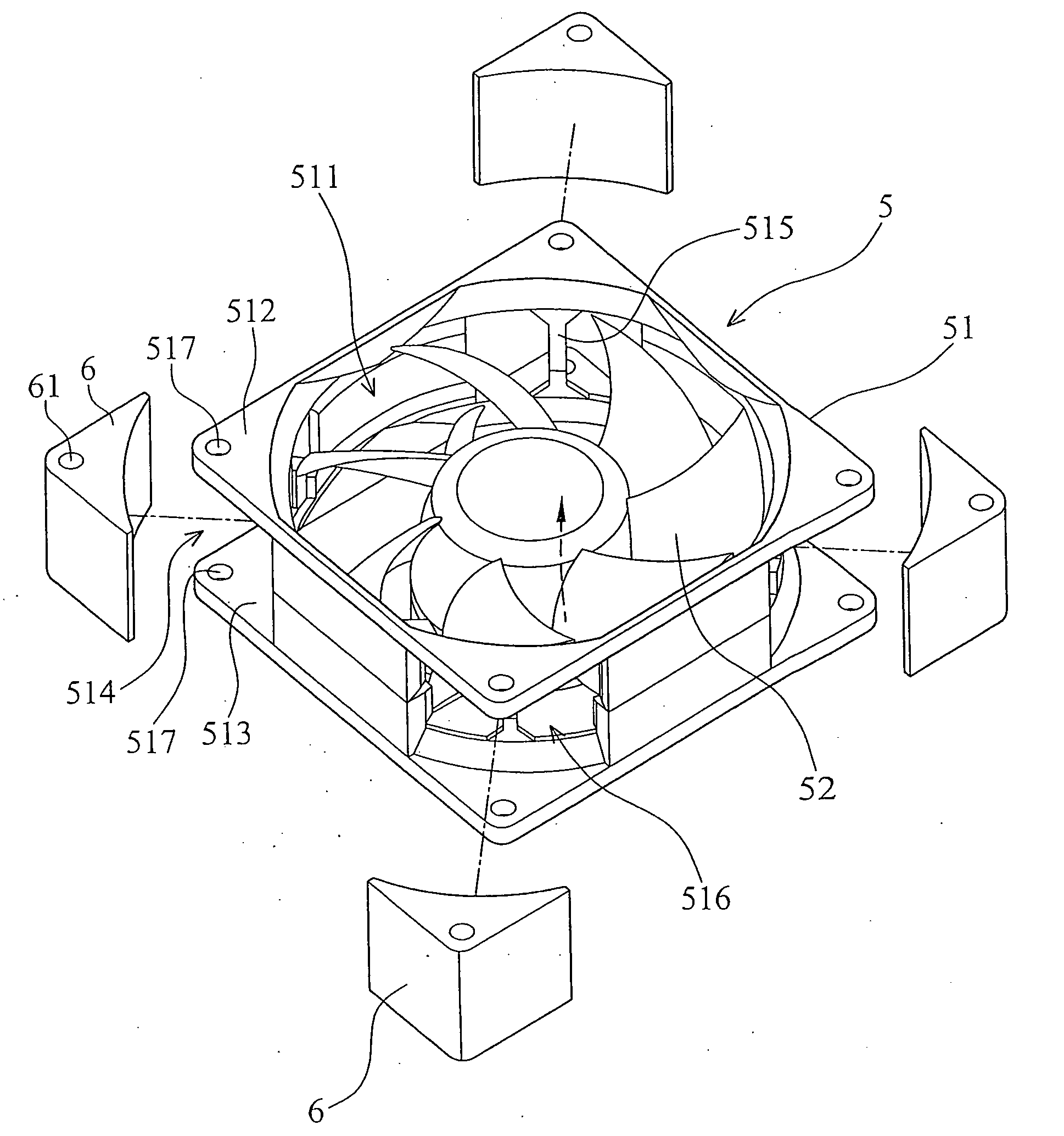
[0022]FIG. 3 is an exploded view of a fan with a sound absorber according to the preferred embodiment of the present invention, and FIG. 4 is an exploded view of the fan shown in FIG. 3 with a cover. Referring to FIGS. 3 and 4, the fan 3 can be used in a computer as a heat dissipating fan, but the example is not limited thereto. In other embodiments, the fan 3 can be applied to servers or telecommunication products. The fan 3 includes a fan frame 5 and an impeller 52 disposed within the fan frame 5. The fan frame 5 has a rectangular main body 51, at least one sound absorber 6 and at least one cover 7 disposed close to the main body 51. In FIGS. 3 and 4, there are four sound absorbers 6 and four covers 7 corresponding to these sound absorbers 6. The main body 51 has a passage 511 formed in the main body 51 for receiving the impeller 52 and the motor (not shown). There are two flanges 512, 513, which are relative to the inlet and the outlet of the fan frame 5 respectively, formed on e...


PUM


Abstract

A fan includes an impeller and a fan frame. The fan frame has a main body and at least one sound absorber, wherein the main body has a passage for receiving the impeller, a plurality of flanges are disposed on a periphery of the main body, a recess is defined between the two adjacent flanges, an aperture is disposed on a wall of the main body corresponding to the recess so as to allow the recess to communicate with the passage, and the sound absorber is disposed in the recess. Also, a cover is assembled in the min body and covers the sound absorber within the recess.

Description

BACKGROUND OF THE INVENTION[0001]1. Field of the Invention[0002]The present invention relates to a fan and a fan frame thereof, and in particular to a noiseless fan with disposition of sound absorbers requiring limited space, successfully reducing noises during operation.[0003]2. Description of the Related Art[0004]Within the field of heat dissipation of electronic devices, fans are commonly used in computer systems and many electronic products mainly because fans are cheap, reliable and efficient. In early years, fans were valued based upon heat dissipating efficiency, but noise produced by the fans were ignored. However, mostly noises in an electronic device originate from fans. As shown in FIG. 1, a standard fan 1 has a frame 101 covering an impeller 102, and impeller 102 rotates to produce air flows for heat dissipation. However, the wall of the frame 101 is made of rigid materials, such as PBT or PC. When the impeller 102 rotates, the pressure at the wall changes periodically, ...

Claims


Application Information

Patent Timeline
IPC IPC(8): F04D29/66
CPCF04D29/66F04D25/0613
Inventor CHANG, SHUN-CHENHSU, CHIA-MINGLIU, WEN-BINYEH, SHIR-HARN
Owner DELTA ELECTRONICS INC
Why Eureka
Try Eureka